ST7735 TFT LCD Goodness
The "widely known ST7735 LCD"
Here in Taiwan there are many indiginous LCD and OLED panel manufacturers, but none of them sell something casually competitive with a relatively ancient (2011) Mainland Chinese panel. It goes by "HTF0177SN-01" from Huanan Electronic Technology Co in Guangdong.
https://www.arduino.cc/documents/datasheets/A000096_Datasheet_HTF0177SN-01-SPEC.pdf
It has 18-bit colour, 128 x 160, and SPI, and its power consumption and 1.77" size is right in the sweet spot.
These have been used for years by Arduino types, and indeed even now you can go to Guanghua, Taipei's electronic otaku district, and buy one off the shelf in Arduino clothing... although it's on an unfortunate crutch board to hide the Arduino's shameful 5V heritage (the panel is natively 3.3V), and unfortunately the crutch board breaks panel readback. The FPC on the module solders direct to the PCB, and it's not hard to remove it and use the panel directly.
Adafruit will sell you one, and you can find them for sale at keen prices with or without the Arduino adaptation junk on Chinese ebay type sites.
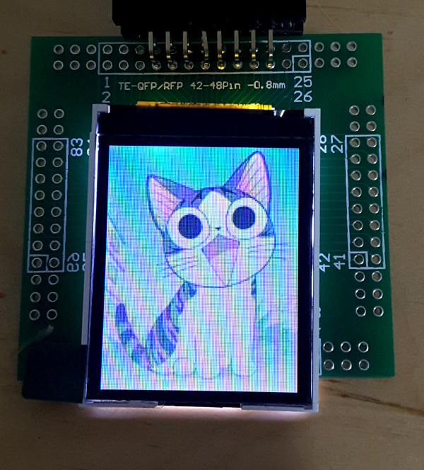
The display quality is very good (much better than the camera captures), although it has quite narrow viewing angle constraints, outside of 20 degrees or so it shows mostly white, without colour or generally inverted.
Adafruit init code
The canonical init code is from Adafruit
https://github.com/adafruit/Adafruit-ST7735-Library/blob/master/Adafruit_ST7735.cpp
however this is pretty abandoned (last real update a year ago, 7 issues + 9 PR ignored) and tied to Arduino.
The various versions of the panel over the years can supposedly be discriminated between by the colour of the tab on the cover of the polarizer sheet: red, green, or black. In the Adafruit sources, some are associated with different chip versions:
| Variant | Vintage | Datasheet Link |
|---|---|---|
| ST7735 | 2008 | http://www.displayfuture.com/Display/datasheet/controller/ST7735.pdf |
| ST7735R | 2009 | https://cdn-shop.adafruit.com/datasheets/ST7735R_V0.2.pdf |
The only difference I noticed is PWCTR1 has 3 arguments on -R and 2 without.
So your panel
has one of two chip variants on it
has chosen how to configure various option pins on the chip by the wiring on the FPC. These we can call 'integration choices'.
Integration choice #1
If you google around, you will read how the panel supports both 3-wire and 4-wire SPI interfaces; the controller chip does (and 8-bit 8080/6800 style async memory interfaces too) but this is not true of the panel you can buy with the controller chip integrated already..
In fact the controller chip gets various config pins tied when he's mounted on his FPC, by the decision of the module vendor, and that controls if he will operate in 3-wire or 4-wire mode.
(What does it mean, "3-wire" and "4-wire", anyway? Basically there is an extra bit required that indicates if the serial byte you're sending is a command (0) or argument data (1).
You could deliver that bit as a 9th (first) serial bit on every SPI data, that's known as "3-wire" then. Or you could just send 8 serial bits as usual and drive a separate pin, known as RS, A0 or C/D, to inform the panel about the meaning of the 8 serial bits you were sending, which is "4-wire".)
Since the wiring of the panel FPC decides it, it's not that there is still a choice, the panel FPC specifically configures the controller chip to use 4-wire mode, so that's all you can use, 8-bit serial data and an extra pin to indicate if it's command or argument data.
Integration choice #2
Another choice that got made by the panel manufacturer is that there is no separate MISO available at the user FPC connector, ie, no discrete data path back from the panel to the master, even though the controller chip provides it.
Instead there is only one serial data pin on the FPC confusingly called "SDA". (Since "SCK" is next to it, the unwary would think they're looking at I2C, not SPI, since these are I2C naming conventions).
In fact both MISO + MOSI at the controller chip are both tied to "SDA": this is legal because the controller defines that only one or the other is allowed to be driven at one time; with this chip you are either shifting a byte in or shifting a byte out, never both at the same time.
The nasty Arduino shield it came with fails to deal with this... it buffers MOSI through a non-3state-capable level-shifter, and does not provide a MISO from the LCD either; together it means the shield deliberately doesn't provide any way to read data back from the LCD. In turn that wilfully removes the ability to read back from the controller its configuration dynamically, which created this wishful thinking about panel tab colours being related in any reliable way to the chip configuration.
If you discard the shield and use the panel directly you can read back using SDA for MISO as well as MOSI.
Note about readback commands
However take note carefully, in the 4-wire mode we are forced to use, the commands RDDID and RDDST insert an explicit extra bus turnaround clock inbetween the end of the command and the data coming back. If you don't take care of it, you will find your responses from these are all shifted right one bit. Curiously other RD* commands do not add the turnaround bit and just work.
My "Green tab" panel reports RDDID numbers of 0x54, 0x80, 0x66 respectively... the non-R datasheet tells to expect the first one to be 0x5c, the -R version datasheet just says -, maybe this indicates with -R or later version the panel factory programs it with their vendor code. At any rate most of the mystery about the canned init sequence application to a particular panel can be cleared away by querying the controller for its situation at runtime.
Integration choice #3
The nRESET signal on the FPC that holds the panel in reset has no pullup. So you must provide your own pullup, or drive it. Otherwise the panel just sits there in hard reset ignoring your efforts to talk to it.
The comment in the canonical init code that seems to claim nCS must be low during the reset is not true on my panels.
Integration choice #4
Another major configuration option on the controller chip is the layout of the panel memory vs the pixels on the panel, this is also decided when the panel FPC is wired in the factory.
The controller actually provides 132 x 162 x 18bpp RAM frame buffer internally: the pin-settable options relate to how the physical 128 x 160 pixels map to the slightly larger memory.
According to the canonical init code, the various tab colours of the panels have different mappings: the green tab is supposed to be offset by (2, 1) but I found that is not true for my panel. So the tab colour cannot be trusted to identify the way the panel configures the controller.
Integration choice #5
Finally although there are 2 x NC pins going spare on the 14-pin user FPC, the panel does not provide the controller chip's TE "Tearing Effect" signal, which is basically an indication of when the panel is performing VSYNC. That means you can't synchronize your logical update of the framebuffer with the framebuffer scanout, by wiring up what is basically a "VSYNC interrupt" to your master.
However, despite the ambiguous entry in the datasheet, it turns out after some experimentation that you can poll the dynamic vsync state using command 0xe, RDDSM. b7 of the first result byte is normally low, and set during vsync. That's a bit awkward, but with some effort it means synchronized updates are possible. Edit: I was not able to reproduce this, b7 simply reflects the state of the TE signal enable bit set by TEON / TEOFF. It seems no way to probe dynamic vsync state without the physical TE signal.
Deviations in the canonical init code
The init code supposed to bring up a "Green tab" panel does not work on my Green tab panels.
The display comes out of reset with vertical stripes, it's the line shift register in the controller just repeated on every line, plus some scary regular black columns that look like dead column multiplexing drivers.
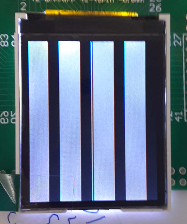
But we don't let little things like that put us off...
Voodoo delays
The canonical init code also suffers from "voodoo delay inflation", the datasheet linked above for the controller specifies 120ms delays for the soft reset and SLEEPOUT commands. But the code
has reset delays of 50ms (ie, too short...) for red tab panels, 150ms for green tab panels on soft reset, and 500ms for SLEEPOUT on both
does a hard reset on the panel by a GPIO first and wastes a further 1500ms toggling that, which has no reasoning
adds a random smattering of 10ms delays during the "red tab" init commands that are not justified by the datasheet (or needed on my panel)
adds 10ms and 100ms delays to NORON and DISPON: the NORON one has no requirement in the datasheet and the DISPON one just says you have to wait 120ms before doing a DISPOFF subsequently.
All in all sweeping away the voodoo delays decreases the panel startup time from 2270ms to just 240ms.
When wandering around hopelessly for a while, reaching for voodoo isn't necessarily a bad idea to see if it affects anything. But once the problem started to shift, it's a good plan to go back and see which changes really affected it (often a bitter process when whole hours of investigation and changes are revealed as contributing nothing useful to the end solution...).
Weird porch padding
Another difference between the red and green tables involved the video scanout timing on the panel... the red tab added a 0 per-frame delay and 3 and 6 pixel-time front and back porches.
But the green tab init changed that to 1 per-frame delay and 44 and 45 pixel-time front and back porches, that's very different: much slower.
On using the red table init for the timing register, for the first time the display did something different involving all the pixels, which was very encouraging. After more prodding and poking I discovered changing it to a per-frame delay of 10 additionally made the raster come out right, showing the video data in the panel framebuffer.
Investigating that further, per-frame delays of 0, 1 and 2 all gave different "broken lcd" displays, but numbers of 3 or above give a working raster.
EDIT: That is true, but the panel suffered from temporary slow "whiteout" type bleaching with the VSYNC number at 3. It caused the viewing angle to degenerate as well. This number is an offset on a fixed starting point of 20 lines for the VSYNC, on my panel 6 seems to be a good compromise.
Wrong SRAM offsets
The init code implies that the green tab panels have offsets of 1 column and 2 rows into the backing store respectively. However on my green tab panel, the correct offset is zero for both rows and columns.
Lack of Hardware scroll window support
In other vaguely similar controller variants there is a line indirection scrolling scheme built into the display controller
http://www.displayfuture.com/Display/datasheet/controller/ST7687S.pdf
however trying those registers on ST7735 didn't seem to do anything. So I think this is absent on the controller the panel actually has.
What did we learn this time?
Panels differ by which controller chip they have on them and the various controller chip integration configurations decided by the panel manufacturer
The Adafruit init code does not work on all panels
only delays mentioned in the datasheet need to be handled, the panel can be initialized in 240ms, not over 2s.
PWCTR1 differs between the two chip variants in how many arguments it takes and the argument bitfield layout
your panel may not follow the offset assumptions in the Adafruit code (they are option pins set by the panel FPC)
When trying to adapt the init code for your panel, be suspicious about FRMCTR1. Wrong numbers here (they can be set wrongly by the controller's reset defaults) get you what looks like a broken panel with vertical stripes
Controller MISO + MOSI are tied together and presented at the FPC as "SDA". It's possible to read back data from the panel.
The Adafruit Arduino shield version just gets in the way and defeats MISO appearing at SDA, it breaks reading from the panel... just bin it and use the panel directly
There are visually identical panel variations that configure the controller chip differently. The best way to identify them is read back RDDID
There is no external Tearing Effect (VSYNC) signal available~~, but you can read the dynamic state via an SPI command~~ Edit: that is not the case, no manufacturer I could find has the panel in both SPI and with TE available.
There's only a fairly narrow "6 O'Clock" viewing angle for correct visual resultsEDIT: if you suffer from this, look at the VSYNC offset number on FRMCTR1. This needs to be above 3, 6 seems to give good results on my panel.Inside the viewing angle though, the panel is pretty good once it's working. The moire in the pictures only appears in camera shots of the panel.