Driving Piezo Sounders
Piezo Sounding
Since we need some audio feedback and alerts, we need some kind of audio transducer on a budget. The cheapest way to do that is a piezo transducer.
Unfortunately that turns out to be a long and interesting story, creating a very long article from what I initially assumed was already a well trodden path.
There are no DAC or other audio arrangements on the CPU (except a heavily pinmuxed I2S we don't have access to), we could fall back to
simple PWM on a gpio
a fixed external oscillator making a beep
a canned buzzer with the oscillator integrated
These will all work but suffer from being kind of basic and crappy.
Like with the video, we have enough FPGA LUTs available we can do something better. However we don't want to over-engineer it... it's the optimum way to do much more than expected with just a little. There is no requirement for high fidelity, we just want to take ourselves out of the shameful world of the fixed beep.
Piezo sounders have some constraints
No useful low-frequency response (really anything below 1.5kHz)
To make 1.5kHz, PWM needs to operate at quite a high rate if all you have is soft-pwm
Many cryptic claims about how to drive them in the internet and complaints they are not loud enough
Care needed: dropping or knocking the piezo can generate some dozens of volts in both positive and negative directions killing your driver hardware
Piezo: the bidirectional transducer
Ehh what was that last one? Yes piezo works both ways, you can flex it with a voltage, and it generates a corresponding voltage when externally flexed the same amount.
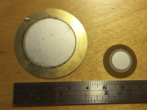
Here is the 40mm sounder in the first pic being tapped gently with a screwdriver

You can see it happily generated +20V / -7.5V spikes just from that, dropping your finished device on the floor may create much more. So the circuitry around the piezo must limit these, effectively, fault voltages. Advice elsewhere on the Internet suggests just selecting 60V rated transistors, but there is no evidence under stress the piezo stops at 60V, or guarantee the next batch you buy won't have different characteristics. So it requires zener / diode clamping to properly control it.
Piezo: the fragile transducer
The active material is sandwiched between a thin brass circle and an extremely thin coating of silver.
Silver is very attractive to solder, in fact the good 30AWG patch wire you can buy for breadboarding is coated with it for that reason.
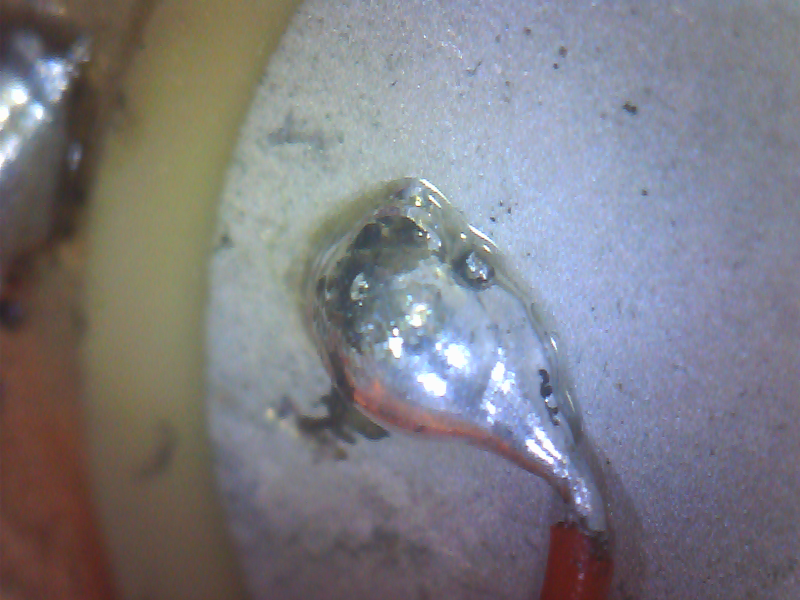
However the plating is like 1 / 30th the thickness of aluminum foil, and like aluminum foil it tears easily; at this thickness even a little bit of heat from your soldering iron will melt it. Unless you want to dig up a furrow on it and ruin the transducer, you need the following approach
reduce the heat on your iron so your solder still melts readily but no more
lay solder on the silver and tin a spot near the middle of the silver, with the iron there for less than half a second
tin your wire
bond the tinned wire to the tinned spot again with the iron there for a fraction of a second just to melt solder to solder
don't let the wires pull or twist off the transducer subsequently
Another kind of fragility is related to overstress on the silver from excessive flexing (eg at too high a voltage): the silver under the solder will simply debond from the underlying piezo substrate en bloc over time, leaving the wire poised uselessly slightly above the transducer and permanently silent.
You can also buy slightly more expensive sounders with an enclosure and bonding wires already sorted out, which is recommended for these and other reasons.
Piezo: the 19th century European transducer
Piezoelectricity was discovered in France in 1880.
But actually it turns out it doesn't work very usefully for audio without the work of a German polymath from thirty years before, Hermann von Helmholz. (he was destined for greatness since his name is the 19th century equivalent of "German McGermanface")
https://en.wikipedia.org/wiki/Helmholtz_resonance
In a nutshell this is what happens when we blow across a bottle and get a satisfying, unreasonably strong response at a particular frequency, even though we just blew white noise across it.
By themselves, with no enclosure, the piezo transducers do not make a huge amount of noise even when driven properly. This caused me a lot of headscratching when I first started looking at them, because upping the drive voltage even to 24V did not really make any difference. It was only when I found a type pre-enclosed in a Helmholz resonator
that suddenly I was able to make sufficiently loud sounds even with 5V switching.
Basically the difference is that of the large sound coming from blowing across a bottle opening, and the sound of just blowing with no bottle there. Anyway the takeaway is you can only usefully use the combination of transducer + Helmholz resonator.
Just use the combined transducer + resonator
There are other problems trying to use the bare piezo "bender" (as they are officially called, no sniggering at the back there) they must be anchored to something and exactly how and where that is done affects the vibration mode and the amount of point stress experienced by the transducer where it is anchored.
The simplest way is just eliminate
- wire bonding problems
- fabrication problems creating an effective resonator
- unexpected impact of strange vibration modes
- reliability issues around flexing and around the wire bonding
- questions of how to anchor
by forgetting trying to use the raw piezo bender, and buying a resonator along with the transducer.
The Thin Spactetime of Guanghua
In Taipei there's a district with a long and sometimes dubious history called Guanghua, this was originally a seedy rundown market-under-tunnels for electronics goods and other, sometimes illegal, things (a garrulous modern-day vendor there pining for the Good Old Days confided to me: guns) back into the 1970s. It's the Taiwanese analogue of the historical Akihabara before it lost a dimension.
 (Photo from Richy at the Chinese Wikipedia, licensed under GFDL1.2)
It became forcibly cleaned up before my family and I moved here, and the previous family market stalls shunted into concrete retail spaces in a large multistory building dedicated to them.
However in Taiwan markets bleed into one another without clear boundaries, there is another section of electronics stores alongside it between it and the Zhongxiao Xingsheng MRT, and there are found aboveground and subterranean stores serving electronics geeks such as myself.
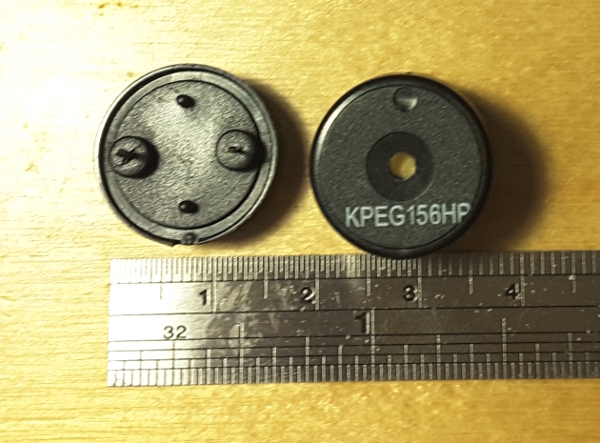
My "KPEG156HP" bender + resonator came from there... like many things it holds the promise of being able to source them inexpensively locally if you can roll 6 on enough dice. But Akihabara, Guanghua... the spacetime they are built on is thin and sometimes things leak across from other worlds. The KPEG156 I have in my hand does not officially exist, the closest the real world dares acknowledge is the KPEG159
http://www.kingstate.com.tw/index.php/ja/component/k2/item/408
That device is specified for 4kHz operation, the overall frequency response is like this (note the log frequency scale)
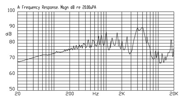
Well you can see from the messy response, it's not reasonable to expect any kind of general fidelity from this. And it is specified for 6Vp-p operation, we will be using it with 5V which is almost there. (This of course is not the same product or exactly the same size, but we can buy these ones from Kingstate in the normal non-Guanghua reality)
Clearly though, within its abilities (ie no low frequency content), you can make more than just buzzing sounds with it, even if you have to give up on classical music.
Driving the element
Piezo elements act like a capacitor, in the case of KPEG159 one of 14nF.
There are many funky schemes out there for driving them, including inductors to make larger spikes; that's fine if all you want are uncontrolled spikes at pulse edges.
However if you want to make more complex sounds, and you don't have a DAC, you are going to have to make a high resolution PWM that can use time to express the level as the ratio between two states. That can be done by basically making a boost regulator with the inductor, but that eats into your time resolution maintaining the boost ratio to create the voltage hike.
Between higher voltage and having a resonator around the transducer or not, the higher voltage is more or less worthless. 5V and the resonator is enough to make loud, controlled, noises with KPEG156 (and presumably KPEG159).
That suits us, since we effectively then need a 1-bit DAC clocked at 48MHz resolution, which can be made from very little logic in the FPGA.
There are several choices about how to go about it:
- 1) Single-ended pulled-up drive
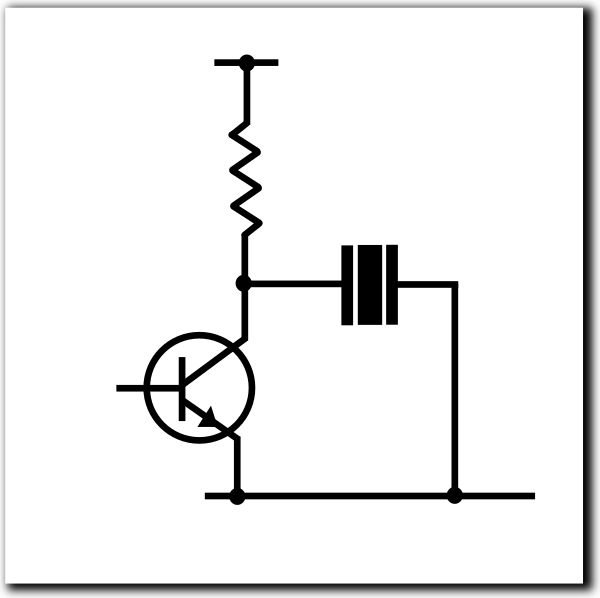
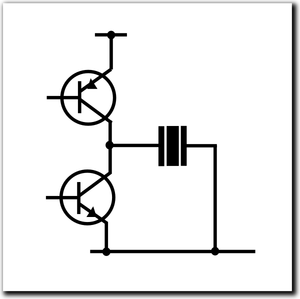
- 2) Single-ended push-pull (aka Half-bridge)
(Notice you have to manage the base drive so the top and bottom transistors are never on simultaneously)
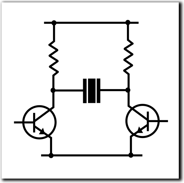
- 3) Bipolar pulled-up drive
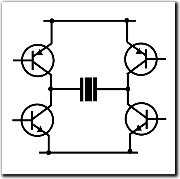
- 4) Bipolar push-pull (aka Full or "H" Bridge)
(Notice you have to manage the base drive so the top and bottom transistors are never on simultaneously)
It boils down to
"drive one side or both sides" (solutions 1 & 2 vs solutions 3 & 4)
"use a pullup or active transistor" (solutions 1 and 3 vs solutions 2 and 4)
The ideal solution is # 4, to use an H bridge. There are two reasons:
- the pullup acts relatively slowly and with an exponential waveform, adding distortion because the PWM ratio loses some time when in the pulled-up state. If we actively drive it, that is eliminated.
For example here, with a 1K pullup on both sides, in the centre of the waveform, when we turn on the transistor we immediately start the "low" part of the PWM in a clean way
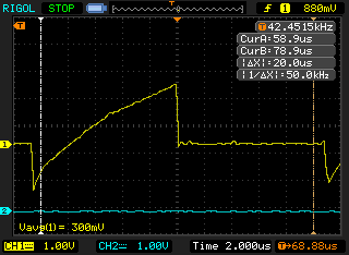
But at the left of the capture, when we turn off the transistor and start the "high" part of the PWM waveform, it lazily ambles high, since it is a passive resistor fighting a 14nF capacitive load. The H bridge would have provided the necessary current immediately to force it straight to 5V the same way that the existing transistor forced it low immediately.
Reducing the pullup to 470R noticeably improves the risetime and the loudness
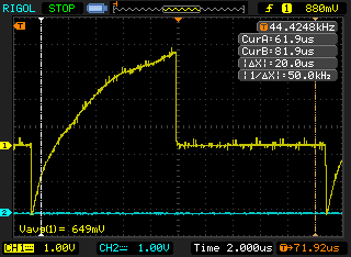
The pullup can be reduced further at the cost of power when the audio is running and maybe noise introduced on the 5V rail.
- the piezo element can flex in two directions depending on polarity of the charge across it. When we use a single-ended solution, we give up half of the potential flex travel (which means, half the noise generating capability) because we can't reverse the polarity of the charge across the transducer in that configuration.
Indeed when you look at catalogue IC solutions for this, they are implementing an H bridge because the incremental cost inside an IC is almost nothing and the advantages are nice.
Although the H bridge is "ideal", it isn't ideal in terms of cost or board space if you are making a discrete solution. In the real world, the third solution is the best compromise considering the other constraints we will discuss next.
Designing the "sound card" in the FPGA
Although I was hoping to experiment with a stochastic solution, where you gate noise from an LFSR using the PWM sample to select or reject it, that will have to wait until we have a GHz design to try it out on.
With this design, the fastest clock we can rely on is 48MHz. So you can do some quick back-of-the-envelope numbers and see what is possible.
Eg, if we wanted 16-bit PWM resolution, the sample rate would be 48MHz / 65536 = 732Hz, which is useless.
At 12-bit resolution, we can get 11.718kHz, which is workable. It can resolve a 5kHz sine fine which is above the ideal resonant frequency for the transducer.
Trying this, driven using a Hyperram FIFO, although it makes sounds well, the sample rate creates a high-pitched, perceptible 11kHz whine even when the samples are all 0.
Therefore I kept the sample rate at 11kHz / 12bps, but split each sample into 4 PWM actions, taking care to dither the two LSB back into the PWM quadrant timing; the sample rate remains at 11kHz, the effective resolution remains at 12 bps but the PWM rate is increased beyond audible range to 45kHz. This comes at some cost in amplitude though... as shown earlier, using the pullup scheme is not very responsive, multiplying the number of times we need the pullup by 4 means a corresponding loss of efficiency. It's still louder than required so no problem.
Clicks and pops
Using the "third solution" of "Bipolar pulled-up drive" also means that the transducer idles with 5V on each side, ie, both transistors are off and no current flows; there is no DC voltage across the transducer since both sides are at 5V.
When we want to play samples though, the initial state and final state of the samples will be signed "0" from the WAV files that are coming from a ROMFS. Since our scheme is fundamentally unsigned, this is corrected in the logic to effectively unsigned 0x800 in the unsigned rand 0x000 to 0xfff.
Therefore when you start or stop playing, you will get a discontiguity from the resting state that corresponds to PWM level 0xfff, and the first sample, which corresponds to PCM level 0x800, and you will get "clicks and pops".
To avoid that, the FPGA logic performs two slow linear ramps from 0xfff to the initial state 0x800 before starting playback, and from whatever the last played sample was before stopping playback, to 0xfff in hardware. This reduces any discontiguity to the point it is inaudible (doubly so since the transducer is unresponsive at low frequencies).
What we learned this time
Forget unenclosed piezo elements unless you're going to put it in some headphones. Only piezo elements with a Helmholz resonator built in are worth considering.
Voltage across the piezo element affects loudness to some extent. But to far less an extent than the resonator, and there are diminishing returns as the voltage increases. 5V is enough to hear it across a room.
The piezo element generates large voltages. Clamp it to within what the drive circuitry can handle.
Using a transistor on both sides driven at 180 degree phase offset, with pullups, is recommended as a good compromise with good results.
You can make a nice "sound card" in an FPGA with PWM. But you must crank the PWM rate beyond audibility, even if the new sample rate remains in the audible range to avoid whines.
Signed 0 samples are disjoint from the piezo resting state of 5V and will generate click and pops when starting and stopping playback. The FPGA automatically performing a linear ramp down and up when starting and stopping suppresses them nicely.