Advantages, Limitations and Costs of Galvanic Isolation
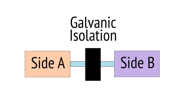
Galvanic Isolation
Galvanic isolation means there is no path for electrons to flow directly between two points.
That doesn't mean current can't pass using "indirect" methods; for example the two sides of a transformer are galvanically isolated, but current on the primary side can be exchanged for a magnetic field, and secondary side may exchange that magnetic field for current that has "no galvanic link" to the primary side; electrons did not pass directly. The magnetic field created on one side efficiently induced a proportionate current on the other side.
 Faraday's original toriodial transformer
This is how come you can plug your phone charger in the wall, which is at a voltage that can hurt or kill you, but you can touch the shield of the USB connector coming out of it without problems, the energy passed through a magnetic intermediary that removed all direct connection to its origin. (This is not 100% true in a real power adapter, as we will discuss in another article).
In Faraday's version, the two sides are not physically connected to each other; the wire is isolated from the metal ring with "cotton and calico". The official term for this is that the two sides are "Galvanically isolated", this is after Lugi Galvani, another European this time from the 18th Century, who discovered the effect of electricity on dead frog muscles, "sparking off" the whole Frankenstein thing.
Advantages of Galvanic Isolation
Floating reference
We say that the isolated part of the circuit is "floating" with respect to the power source. Since there is no direct path for current to flow back to the power source, there is no way to keep it aligned to any reference relative to the power source. It's similar to a balloon that has nothing tethering it.
Instead it weakly finds its own potential according to whatever tiny leakage currents are available - if you connect it to something, it will immediately align itself to the potential of whatever you connected it to. In itself, it won't put up any resistance to adopting that reference; it is not connected directly to anything that could provide resistance.
A familiar case of galvanic isolation is a battery-powered instrument like a multimeter, since it has nothing fixing its reference potential it will float to whatever reference it is connected to; for example in itself a battery powered multimeter can be directly connected to the mains for measurements. It still works because it is floating at the mains potential, so its "0V" is at the mains potential, and its battery is "mains potential + 9V". Local to the multimeter nothing changed.
Break grounding loops
In a building (especially between floors), across a building and sometimes even in a room, the earth reference at the mains sockets it not at the same potential everywhere.
That means if they should be connected together, for example by plugging different equipment together even if the connection is indirect, current will flow through the connection.
This can cause mysterious 50/60Hz hums, unexpected sparks, crashes and shocks when connecting cables etc.
If the connection is via galvanic isolation, this kind of issue is eliminated.
Gotchas of Galvanic Isolation
This isolator isolates in itself, but...
"in itself" may not be the whole story, there may be other external connections and relationships through those connections that can pass current directly, bypassing the isolation.
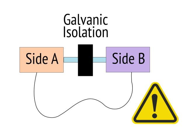
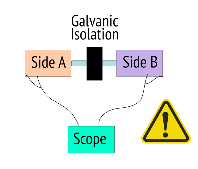
For example your battery powered instrument may become completely un-isolated if you plug in a USB connection to your PC, or plug in a charger, or you accidentally left a 'scope ground probe connected somewhere.
It's the user's responsibility to make sure the isolation can be effective in the larger system safely.
The two sides are isolated via insulation, but...
Nothing is a perfect insulator, but many things have such high impedance they can usually be counted as infinite for some set of purposes.
However -->
No direct path for electrons to flow, but...
There will be a breakdown voltage at which the insulation will break down and conduct, arcing over. This is a particular consideration trying to connect to mains with isolated equipment, since the mains is nominally 110VAC or 230VAC, but can experience excursions many times higher if you, eg, plug or unplug the equipment or other mains equipment on the same ring.
So the degree of isolation must be qualified with the maximum voltage below which the isolation is guaranteed to not break down. Often this is in the hundreds of volts or kV range, although that also must be qualified as the whether it's talking about DC or AC and for how long it can withstand that potential difference. If there may be excursions, you will have to do something to snub them.
DC carbonization / tracking
There is also a breakdown mode related to formation of conductive carbon deposits between conductors that have a high DC potential between them for long periods... this "tracking" that forms is like a kind of soot. I'll discuss that further in a related article.
If you will use isolated equipment that has dangerous potentials between the two sides, you must concern yourself with these and other details and safety arrangements.
Isolated system architecture
A system involving galvanic isolation usually has two things that must cross the barrier, power and data.
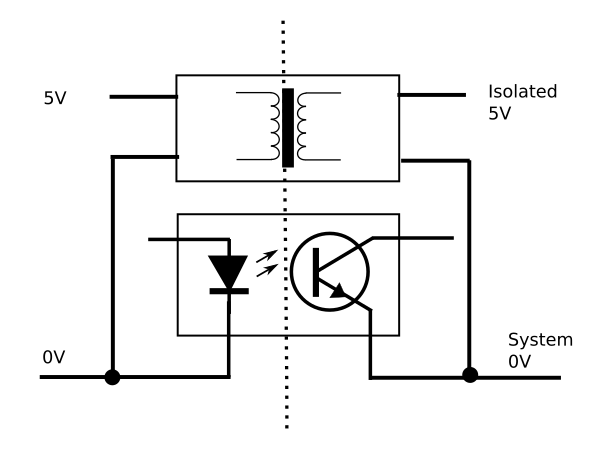
And in the overall system, there will be two "0V" references, one on the nonisolated side and the other we can call "System 0V" on the isolated side.
Passing power between isolated domains
Isolated DC-DC converters are available quite cheaply and quite compactly for up to 1W. Inside the insulated package, they contain a tiny toroidial transformer very much like Faraday's. They are rated for isolation voltages from 1kV to 3kV usually.
Communication between isolated domains
There are several ways to communicate across the isolated domains without a galvanic connection.
| Method | Description | Advantages | Disadvantages |
|---|---|---|---|
| Optocouplers | LED and optosensor sealed in same package | Offers isolated bipolar transistor output | Expensive for many channels and may consume power like an LED |
| Capacitive couplers | Modulates high frequency RF carrier with the incoming signal, passes it over a capacitive barrier, demodulates | Digital (usually 3.3V) semantics, relatively cheap for many channels | Only digital semantics (no bipolar option) |
| Transformer | Passes data in the magnetic domain | cheap for one channel, can include voltage conversion | requires AC or modulated data |
| Explicit RF | WLAN or BT etc | no physical connection | not suitable for for intra-device connections, expensive for whole stack |
What we learned this time
Normally equipment must share a common reference voltage ("0V" or "Ground") to be powered and to communicate
Isolated DCDC converters and various techniques for communication across isolated domains let you get around that
The isolation is rated for a particular voltage beyond which it will "break down". This is often in the 1 - 5kV range.
If the galvanic isolation supports your worst case voltage differential, it allows you to work on circuits with radically different potentials, including circuits directly connected to live mains. It doesn't make any other danger magically disappear though, you must take responsibility for all necessary precautions regarding hazardous voltages.
Having no galvanic connection is useful for eliminating "ground loops" that may otherwise cause intractable problems
You have to ensure your isolated side really is isolated, considering any connections it may have in parallel to the galvanic isolation, eg, scope probe grounds. Otherwise the isolation is bypassed.