HDMI Capture and Analysis FPGA Project 2
Part 2 / 6: HDMI on the wire
Details of HDMI protocol layers
So I guess readers know broadly how DVI and HDMI work in outline, it serially transmits pixel data that's reconstructed at a receiver.
But there are a surprising amount of details and room for implementation differernces.
At the bottom-most layer is the electrical interface.
TMDS33
DVI and HDMI specify that the same differential signalling is used on all the high-speed lines. Differential signalling is a very old and good technique for increasing signal to noise and resitance to common-mode noise. In the olden days transmission lines using this method were called "balanced".
Instead of sending the signal on one wire (referenced say to 0v), you send the signal on two wires, known as + and -. The - signal is the same signal as +, but inverted (so if + is 1, - is 0 and vice versa). When the signals are combined, "common-mode" noise, noise that appears on both signals the same, tends to be cancelled out. And when differential signals are routed for long lengths, the wires are twisted togther so their emissions also tend to cancel.
HDMI needs more bandwidth than can be sent on one differential pair. So they use 3 data pairs and one clock pair, plus some auxiliary signals. (Two of the auxiliary signals are also in a twisted pair physically, but they are not TMDS33 or related to the HDMI data stream.) In total there are 19 conductors in the familar HDMI cable.
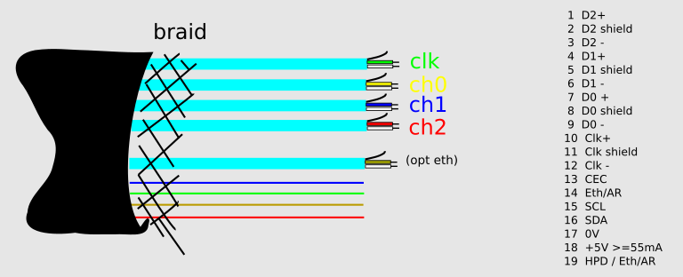
In DVI and HDMI the 3 data lanes and the clock lane are differential pairs using TMDS33 levels. TMDS requires 51R pullups to 3.3V at the receiver. However the differential voltages themselves are much smaller, on the order of 100 - 200mV. Smaller levels are quicker to reach and allow faster transmission rates.
The presence of these termination pullups is detected by the transmitter and it may suppress data transmission until they are seen, known as "receiver detection".
My 'scope is too weak to record the data faithfully at 742.5MHz clock used in 720p, but below gives you an idea of what the differential signals look like when pulled up to 3.3V and transmitting.
It also shows how inadequate a 200MHz bandwidth scope is for looking at this, there are actually ten bit-times shown between the two vertical lines (roughly one 74.25MHz period). HDMI receivers (and the FPGA used here) have higher bandwidth inputs that can resolve the individual bits properly.
TMDS33 Channels
The DVI or HDMI cable itself carries the clock pair and three data pairs that transmit in parallel.
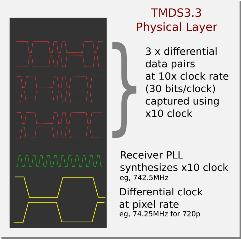
Although the actual clock rate is very high, to ease carrying the clock on real cables and reduce RF emissions, the clock that is sent on the HDMI clock differential pair is 1/10th of the rate of the data on the data pairs. This makes the HDMI clock period represent one pixel period, in other words considering there are three data channels, there are 30 bits transmitted per HDMI clock period (== per pixel).
A PLL in the receiver reconstructs the x10 clock and uses it to capture the data on the channels.
TMDS codings
Unlike a VGA or earlier cable, there are no wires reserved to carry the sync signalling. Instead, syncs are carried as part of the 10-bits per pixel data from each channel, and they are carried differently according to what else is being sent.
The reason for this is that HDMI is derived from the earlier DVI standard, which had a very simple plan for carrying the syncs using reserved symbols during the whole of the blanking period. But HDMI builds on DVI by allowing new "data islands", using a different coding scheme, to randomly be carried during blanking as well as "control periods", and makes explicit "video periods" that contain the active video data: since DVI doesn't have these extra concepts it means HDMI ended up with two (syncs cannot change during active video data) completely different ways to express HSYNC and VSYNC state in the stream.
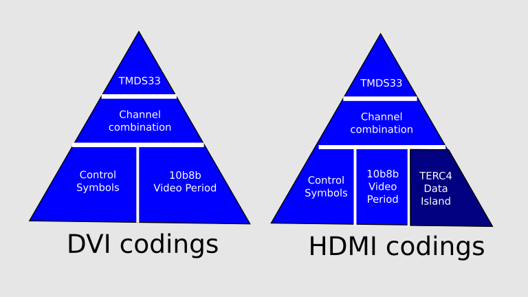
The direct logical codings in HDMI then are
- Active video data using 10b8b coding (providing 8b each for RGB in RGB mode)
- Control periods using one of four special 10-bit control codings to express the 4 possible HSYNC + VSYNC states (10b2b)
- Data islands using TERC4 (10b4b) coding
During the active video region where pixel data is being sent and 10b8b coding is used, there is actually a choice of two codings per byte. Once choice has more zeros and the other more ones. The transmitter selects which coding to use per pixel based on whether it has sent more ones or zeros lately, it keeps a running count and selects the coding to keep the ratio of ones to zeros at 50:50 overall.
TERC4 is a sparse 10b4b coding that is used to carry both HSYNC and VSYNC data and generic data such as HDMI audio samples. TERC4 has its own structure and subchannels, and inside the overall 36-byte packets sent using it, various packet types can be found (including PCM or other audio samples).
Although the Conrtrol Period reserved symbols are unique, actually you can't interpret HDMI data overall without parsing what has been going on before to eg, understand you are in an active video period or data island and track it using a state machine.
Types of stream sync in HDMI
At the high data rates of HDMI, skew between clock and data, or between data channels, or between differential pair members on a single channel or clock can destroy data integrity. These skews depend on the transmitter and cable as much as the receiver, and they vary somewhat with temperature.
So receivers typically have to hunt for the best clock phase with the least error rate... FPGAs have some support for either delaying to clock or individual data channels by small amounts to compensate. All high speed serial buses have some need for this including DDR, SD and PCIe who call it "tuning" or "training".
If we are able to collect bits with low error rate, we need to decide which on the 10 bits per HDMI clock is the first bit. This can be done by trying all 10 and finding out which exhibited the most valid control period symbols.
At that point we are aligned enough we can receive the 30 bit pixel data as it was sent.
The reserved control symbols are then used to align to higher level decoding state to track where we are in the raster, since they don't appear in either TERC4 or 10b8b data.
Refresher on generic video timing
The structure of video streams is still basically the same as used in the first black and white TVs, with CRT type displays.
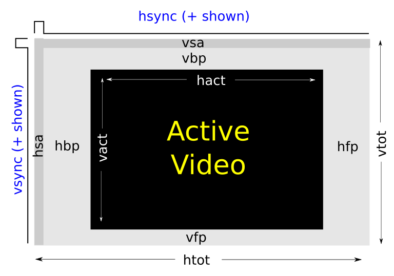
Basically, there are two kinds of period, active video (black) and blanking (grey). Normally only the active video part is shown on your display, but for our purposes, we are interested in capturing ALL of it.
Originally the blanking was used as the time required to swing the electron beam illuminating the CRT phosphor back to the start of the next line (on HSYNC) and back to the top left (on VSYNC) and it had no other purpose. On analogue TVs audio is sent separately on a different but related frequency. When Colour was added in analogue video, a chroma burst used to sync the phase of a chroma subcarrier was added in the back porch of each line. The sync pulses were encoded as different analogue voltage excursions not used by the video part.
Digital video formats kept the basic HSYNC and VSYNC timing and the concept of blanking intervals. So they still have front and back porches and HSYNC and VSYNC durations. One of the reasons the blanking interval won't die is because it allows you to tune the refresh rate of the video at a given pixel rate without changing the active region; this is how it is possible for HDMI to do both 720p50 and 720p60 using the same 74.250MHz pixel clock... the active video area is the same but the amount of blanking pixels is traded off with the time needed to send ten extra frames per second: 720p50 has an artificially large blanking period as you can see from a real capture below.
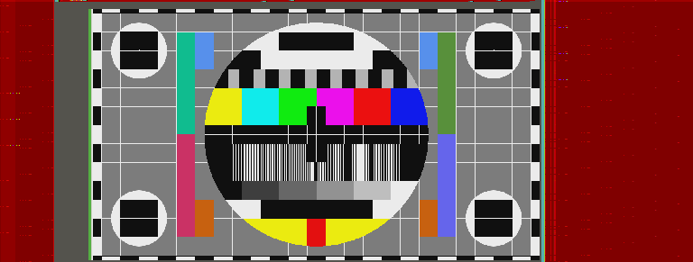
It actually uses 1980px for each line even though only 1280px contain active video.
Once it was decided that there was an unused blanking interval basically as padding, in a digital protocol naturally minds turn to using the data passed there for something good. On DVI it simply passes 10b2b control period codes that encode the HSYNC and VSYNC state. On HDMI you can still do that, but you have the option to place "Data Islands" in the blanking (these are the red areas in the picture above). After error correction codes are removed, these consist of a 3-byte header and 4 x 7 byte subpackets.
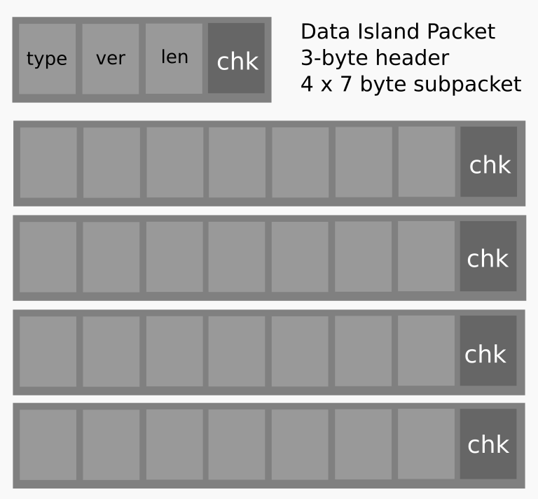
The three-byte header is defined in HDMI to contain a packet type, version and length information, and there are a list of packet types such as those carrying PCM Audio samples: at 24bps, the 4 x 7 bytes is enough to carry the 8 channels supporred by HDMI with 4 bytes left over.
Because HDMI sends these data islands using TERC4 (10b4b) on 2 of the three channels, and including error correction, 36 bytes must be passed, each data island packet "costs" 36 pixel-times of blanking plus some overhead to start and stop a data island in the protocol. During this time, the other data channel is used to send HSYNC and VSYNC state also in TERC4.
HDMI defined Data Island Packet Types
HDMI defines the following packet types... it's legal to just ignore them and act like it's DVI, if your HDMI sink doesn't need features like audio. However we are interested in audio and the other information.
| Type code | Type meaning |
|---|---|
| 0x00 | Null |
| 0x01 | Audio Clock Regeneration (N/CTS) |
| 0x02 | Audio Sample (L-PCM and IEC 61937 compressed formats) |
| 0x03 | General Control |
| 0x04 | ACP Packet |
| 0x05 | ISRC1 Packet |
| 0x06 | ISRC2 Packet |
| 0x07 | One Bit Audio Sample Packet |
| 0x08 | DST Audio Packet |
| 0x09 | High Bitrate (HBR) Audio Stream Packet (IEC 61937) |
| 0x0A | Gamut Metadata Packet |
| 0x81 | Vendor-Specific InfoFrame |
| 0x82 | AVI InfoFrame |
| 0x83 | Source Product Descriptor InfoFrame |
| 0x84 | Audio InfoFrame |
| 0x85 | MPEG Source InfoFrame |
0x83 (SPD) is quite interesting, the source device can send a vendor and product description in ASCII. On my laptop, it sends "Intel" and "IntegratedGfx".
Continued
Now we discussed the problem and the wire protocol, the the next part discusses how the solution was implemented on FPGA side.
