MIPI I3C
MIPI I3C

I3C is a new MIPI standard aimed at replacing I2C and SPI in low-cost devices. But right now, the actual standard is only available for MIPI members, not mere mortals. This article is a summary of what I could find out about it.
I2C and SPI
I won’t go into I2C or SPI since interested readers will already know those well, except to note:
I2C is a slow 2-wire + GND, multidrop, Open Drain, interface, and SPI a faster point-to=point 3 / 4 wire + GND interface with separate select signals per peer.
I2C starts at 100kbps and extends to 3.4MHz; SPI can be clocked much faster with eg, serial flashes that can be clocked at 80MHz and above.

I3C base signalling
I3C does not have anything in common with other MIPI low-voltage signalling standards like PCIe, DSI, CSI, UniPRO, which use low-voltage differential signalling. The signalling is single-ended with HCMOS style levels.
I3C is similar to, and is mostly backwards-compatible with, I2C with some extra “modes”, the same way SD Card interface can negotiate faster modes.
Like I2C there is an explicit clock signal and a data line, but the clock signal is defined to be push-pull (< 0.3Vdd = 0, > 0.7Vdd = 1) in all new modes
Therefore I3C does not support the intrinsic level-shifting capability of old I2C (circuitry at different Vdd could communicate because the two signal levels were “nearly 0V” or “something else”)
Pullups are no longer needed if you are not dealing with legacy I2C-only slave devices on the bus
I2C “Clock stretching”, where a slave could delay the clock until it was ready, has been eliminated
Otherwise I3C is close enough to I2C if you reduce the clock accordingly, you can use it with most existing legacy I2C devices.
The “Base” mode, I3C SDR, allows up to 12.5MHz with either OC or Push-Pull data drive, it’s very close to “fast I2C”.
Slaves may detect an idle bus and issue a synchronous interrupt on the bus with contention resolution. The slave transitions Data to do it, only the master provides the clock.
I3C backwards compatibility with I2C
I2C devices have been around since the early 1980s, and many mature slave devices are simply not going to be updated for I3C. So “enough” backwards compatibility in the master was critical. Few I2C devices use clock stretching and the loss of it in I3C can be worked around by slowing the clock from the master side if needed.
The level shifting is more of a loss for some cases, but even then I2C’s Open Drain scheme was always difficult to buffer, needing specialized chips, eg PAC9306. If both clock and data are push-pull now, generic level-shifting is possible. Although the latency will increase, potentially impacting the max clock rate.
The “faster cock modes” even of old I2C rely on I2C devices that can’t handle them rendering them invisible using their “glitch protection”… if a signal doesn’t maintain its state for, eg, 50ns it is ignored by the slave.
But what about newer slave devices that come out with I3C interfaces, when all the masters available today are I2C-only? It’s unclear if I3C slaves can be used by I2C masters… the signalling is compatible but there is not enough info about it to understand if, eg, I3C slaves can present a oldstyle I2C address by default.
10-bit address mode slaves are not supported. But these all have 7-bit fallback modes anyway.
I3C addressing
I3C devices get standardized “characteristics registers” and a 48-bit “mac address”
Devices are “discovered” dynamically
Devices may join and leave at any time, and are discovered and dynamically addressed accordingly
There’s still a 7-bit address, but this operates dynamically as devices are discovered like the USB device address; fixed I2C 7-bit addresses are eliminated unless it’s a legacy device.
I3C defined commands and error management
DSI-style “command mode” with standardized commands and payloads, may be broadcast to all peers or addressed to a single peer - this is the basis of the discovery protocol
Both master and slave can report standardized “errors”, including parity and CRC
I3C SDR
SDR / Single Data Rate signalling is I2C signalling with push-pull clock and optional push-pull or Open Drain (for backwards compatability with I2C) data
it’s specified for up to 12.5MHz clock, although how acheiveable that is depends on the capacitance of the loads, how many loads, wiring length and allowable error rate.
I3C HDR
The I3C bus can enter and exit sigher speed modes using a special SDA-only sequence of repeated STOP / STARTs (modern I2C devices have something similar where you can send them a special command that transitions to 3.4MHz, but the I3C scheme is baked into the protocol). I3C devices get a broadcast message saying we’re going to transition to high speed (EnterHDRx) and then the SDA sequence. I2C slaves see STARTs and STOPs and then ignore the fast clocking on SCK.
The EnterHDRx message can tell the I3C devices to enter either “DDR” mode or “TSL/TSP” modes… this is extensible since new modes can be sent on EnterHDRx and devices that don’t understand them just ignore until they see the SDA-only exit pattern.
I3C HDR DDR

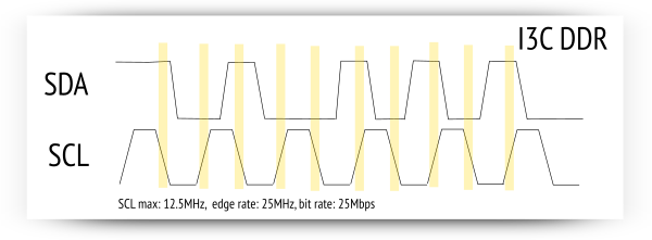
In DDR mode, a new SDA is samples on each SCL clock edge, and since START and STOP are then no longer possible, a structured packet, which includes parity, is used to communicate.
When finished using the high speed mode, the SDA-only exit sequence is sent and the bus reverts to SDR mode.
Normally, DDR requires a PLL, but I2C has traditionally been parseable using asynchronous logic alone. It’s not clear from the available data if something else about the sequencing mandates a PLL to recover multiples of the clock rate, and then implies a predictable, phase-locked clock on the wire, making bit-banging impossible.
I3C HDR TSL / TSP (ternary)
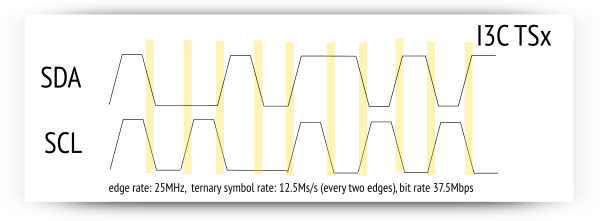
As well as DDR above, where SCL is still basically controlling sampling of SDA, I3C supports ternary coding modes… in this mode, SDA and SCL are treated as two data bits which are sampled together. However between each ternary symbol, at least one bit must change state.

Another way of looking at it is from each 2-bit symbol, there are three possible next symbols… 00 may become 01, 10 or 11 and still meet the requirement for at least one bit to change state.
We have to wait for more info from the standard to describe exactly how, but two 2-bit symbols together can encode three bits, with the overhead used for the clocking.
TSL stands for Ternary Symbol Legacy as opposed to TSP for “Pure”, so I guess “Legacy” is less efficient in an attempt to avoid bus states that old I2C might misinterpret. But it’s also not explained yet that I could find. This efficency loss is likely the reason the max bit rate is “over 30Mbps” in the marketing claims, not “37.5Mbps”
| mode | rate | max throughput |
|---|---|---|
| SDR | 1 bit / CLK | 12.5Mbps |
| DDR | 2 bit / CLK | 25Mbps |
| TSx | 3 bit / “CLK” | 37.5Mbps (“over 30Mbps”) |
(There is no “clock” in ternary mode, but it transfers 3 bits in 2 “edges” on either / both SCK + SDA).
I3C Synchronous bus reservation
The specification also defines USB-type bus reservation, so you can define that you will have bandwidth at a certain time to talk to a certain device.
What did we learn this time?

I3C is a more-or-less backwards-compatible enhancement to I2C
It offers DDR and Ternary modes to get >30Mbps from a ~12.5MHz clock, without using LVDS
Because it dispenses with I2C pullups, simply by mandating push-pull for newer modes, it can claim huge power savings over I2C. But those savings don’t exist compared to, eg, SPI.
It claims to replace SPI, but it provides no backwards-compatibility and the max clock rate is slower than SPI provides. SPI remains a competitor to I3C. Still, it will likely push SPI out of any usage where I3C will do.
I3C takes ideas from DSI (command packets) and USB (bandwidth reservation and discoverability / hotplug), but the bandwidth reservation is just a controller feature not baked in.
AFAICT you can still bitbang it, although we have to see about DDR and if it gets implemented with a PLL in the slave devices
I2C backwards-compatibility lacks support for 10-bit addresses, inherent level-shifting, and the slave device holding the master clock down. Otherwise it encompasses I2C compatibility, athough the whole bus will slow back down to 100 / 400kHz when you talk to them.
There aren’t any I3C devices you can buy off the shelf at digikey or mouser yet. But it’s a safe bet I3C will replace I2C-only interface units in SoCs shortly.
Slave device vendors will stick with I2C where I3C features are not needed; I3C masters can integrate them on an I3C bus. Slave devices that suffered from the slow max clock rate of I2C will likely move to I3C. Slave devices that only used SPI for the better clock rate, but the speed they needed is now available with I3C, will also likely switch to I3C.
