Generic MOSFET Power Switching
Generic Mosfet Power Switching
Digital developers usually deal with low DC voltages around 5V, but there are also higher voltages (12V, 19V, 24V) in less common use directly, and as the input voltage to be regulated down to the lower voltages. Therefore typical bench PSUs are able to provide voltages at least between 0 - 30V.
If you want to be able to control that arbitrary range of voltages, for test or as part of a developer write - burn - crash testing loop, you will need generic DC power switching - turning DC on and off - over the range 0 - 30VDC and up to say 3A. (3A is conveniently the rated current for 0.1" box connectors).
And in our case, we want to do it isolated from the on-off controller, which operates at digital voltage levels unrelated to 30V and indeed an unrelated ground reference.
After the isolated DC-DC and digital isolator (optoisolator, capacitive isolator or whatever) for the control signal, we can just throw a big MOSFET at it, right?
Well, let's compare a humble relay to that kind of solution...
Relay Race
| Feature | Relay | MOSFET |
|---|---|---|
| Isolation of switched power from control signal | Yes | No |
| Tolerant of spikes and transients | Yes | No |
| Four-quadrant power switching (current +/-, voltage +/-) | Yes | No (blows up at high currents) |
| Low insertion loss to switch | Yes | Usually |
| Requires 0V reference of switched voltage | No | Yes |
| Fragile against short transients without precautions | No | Yes |
| Automatically OFF when unpowered | Yes | Not in one direction |
| Switching speed | ms | us or ns |
| Switching bounce | Yes | No |
| Marketing value | low | higher |
Ehhhhh....
Relays have their own problems, there is a gap between ones capable to switch 2A and those capable to switch more. The 2A ones are available in convenient sealed SMT packages, but above it they are packaged in larger automotive style chunky rectangles.
They have contact bounce, and as electromechanical devices, eventually suffer from various failure modes like the contacts corroding. Switching DC accelerates some of them; for that reason a relay rated to swith 277VAC may only be rated for 28VDC. In fact DC is a big problem, typical relay datasheets specify a "minimum recommended contact load" of ~100mA at 5VDC, we do not want to burden our users with that kind of restriction for the generic case. In both cases it's related to electrochemical effects at the contact points of the relay switch.
Relays don't sound good for marketing purposes either.
There are optoisolated "solid state" relays, which are integrated MOSFET solutions, but these are VERY pricey for low on-resistance. And without the low on-resistance, they get hot. US$35 will buy you one that tops out at 2.5A and 24V, which doesn't meet our goals.
So what are the underlying problems a MOSFET faces with this generic switching task?
Problem 1: Requirements of Gate drive
MOSFETs are used everywhere in electronic equipment for power control. Can't we just use an off-the-shelf IC for gate drive? This looks good at first sight
http://www.ti.com/lit/ds/symlink/lm9061.pdf
There are many nice gate driver ICs which can be used for both N and P MOSFETSs, and include their own charge pump to provide the necessary gate voltage.
Well, these solutions don't work for switching input power down to 0V relative to system 0V. They assume that
the job they are doing is a buck regulator, that is regulating a higher voltage down to a lower one
the switching is rapid and continuous as it would be in a buck regulator, perhaps up to 2MHz, which implies PWM type gate modulation, which is coupleable by transformer... not what we are doing
the gate driver is powered from the rail being switched (it must at least be connected to it).
they disable themselves if the input voltage to be switched is what they consider to be "undervoltage", usually >5V
This last 'feature' is highly desirable in the case we're a regulator switching from a low battery, or a decaying source power supply that has been switched off, and enabling the switch should be forbidden. But for the 0 - 30V target, it renders the solution useless: in some cases like the TI chip linked above, the undervoltage threshold is as high as 7V; we can't even switch 5V with that. Plus then the charge pump is powered from the switched power; we just want to turn it on or off, not consume it.
In our case we have our own isolated power we need to run the switch from, and we need the power switch side to work independent of the voltage being switched (in the valid range 0... 30V).
Whereas relays have no problem with needing special bias for what they are switching, P MOSFETs require gate switching below 0V (typically -10V for full enhancement) and N MOSFETs require gate switching above the switched rail (again typ +10V above the switched rail). The integrated solutions provide a charge pump in the IC, without that some other way is needed.
Discrete solutions for this kind of non-mainstream MOSFET usages are therefore common, there's a really excellent article exploring the various permutations here
http://www.radio-sensors.se/download/gate-driver2.pdf
As the author says
''All these difficulties make the high side driver design a challenging task.''
Problem 2: Importance of enough gate margin to "enhance" the MOSFET
Switching low voltages at high currents really requires these 'difficult' gate voltages, either 10V below 0V or above the switched voltage. If you try to switch using 0V or the rail voltage at the gate, as the switched voltage decreases the voltage between the Source and Gate will likewise decrease until MOSFET will find itself in the linear region, where it is not fully "on" and enhanced any more, but is restricting the current that may flow proportional to the gate voltage. In the worst case where the resistance of the MOSFET is equal to that of the the load, the MOSFET will dissipate (V/2) * I, for V=2V (typical linear region Vgs) and I=3A, that means 6W as heat. So we need to not be in the linear region of gate voltages.
If the MOSFET is instead always fully enhanced by the "difficult" ~10V gate-source voltage, at low voltages the heat dissipation is negligible because the on resistance is 10mR for P or as low as 75uR for N.
Problem 3: Driving gate capacitive load
Increasing the danger of finding yourself spending too much time in the dangerous linear region of the gate potential is the capacitive nature of the gate itself. You basically have to modify the gate charge, which is an RC type activity whose speed depends as much on the impedance (the R part) of the drive voltage you want to change it to, as it does the gate's intrinsic capacitance (the C part).
The larger (more power-capable) the MOSFET, the higher the gate capacitance.
To change the gate charge quickly then, so we slew through the linear region in ns rather than ms, the gate drive must have access to a low impedance power supply at the right level, where the "right level" is "Source - 10V" for a P Channel MOSFET, and it must actively switch the gate drive... pullups are too slow since they form an RC network with the gate capacitance.
That is not so simple to provide, when the MOSFET Source the gate drive is referenced to may itself be anywhere between 0V and 30V compared to the system 0V (and the system 0V may be floating compared to the digital control side).
P and N channel MOSFETs as High Side Switch
P and N-channel MOSFETs are analogous to PNP and NPN bipolar transistors. N-channel MOSFETs are cheaper than P ones, and have lower Rdson (enhanced on-resistance). You can use either as the switch, the main impact is then you must come up with either switched voltage - 10V (P) or switched voltage + 10V (N).
As you can see, these voltages are not referenced to the system 0V but to the switched voltage, ie, the MOSFET source. Any MOSFET will immediately, permanently die if the gate voltage should ever exceed a maximum permitted source-gate voltage, usually around +/- 20V compared to the source; this is scary seeing as our input range encompasses 30V. It's also scary because violations as short as 1ns will kill the MOSFET, at 30V hotplug transients can easily manage this if there are no steps taken to protect it.
Normally the voltage being switched is already decided inside some equipment and this can be figured out. But in this case the voltage being switched is something random in the range 0 - 30V. And we do not want to load or impact the voltage we are switching any more than necessary, meaning we want to generate the gate voltage from our own isolated power.
Problem 4: MOSFET Switch only works in one direction
With the Humble Relay, there is no intrinsic polarity to the two sides of the switch, both sides are interchangeable.

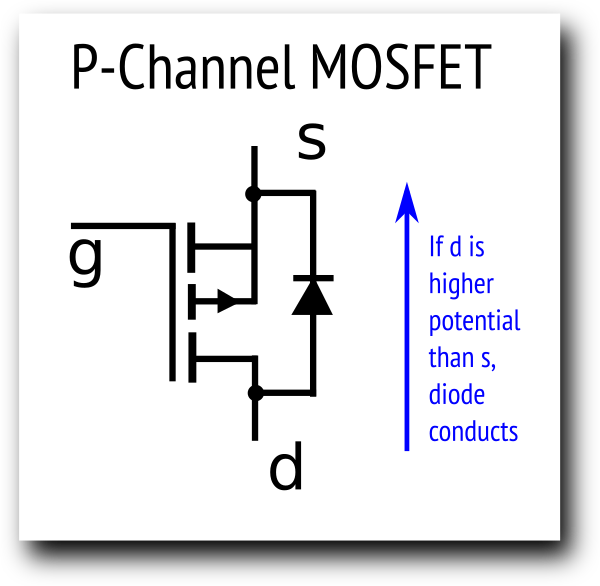
But with a MOSFET, he has a giant parasitic diode between D and S. That means if there is a MOSFET between them, the two sides of the switch are quite different, one must be more positive than the other for normal operation. What happens if they are the "wrong" way around is that even when the gate is not driven, the parasitic diode conducts and the switch is effectively "always on".
If there is a high load (3A in our case), the diode voltage drop translates to a large heat dissipation at the MOSFET, and we can't turn it off, since the diode is unconditionally conducting under those conditions. So the MOSFET will just burn.
Problem 5: Negative Voltage at input unprotected
Again, the Humble Relay doesn't care if you are switching voltages below 0V or indeed what the voltages are referenced to, if it doesn't make the relay insulation break down. In our case we only support positive voltages compared to system 0V, but as it stands with one MOSFET doing the switching, again the protection diode will conduct and we lose control of the conduction and heat generation at the MOSFET.
The most common case for this in the real world is someone reversed the input power polarity. We will continuously pass it (minus a diode drop) and blow up his attached equipment and maybe our MOSFET.
Problem 6: MOSFET solution needs 0V for switched side
If we just have a simple MOSFET doing the switching, for all normal solutions the 0V the switched voltage is referenced to is required, as part of the gate voltage generation. In contrast the relay doesn't care, contacts are either shorted or not: what the voltage on the contacts is referenced to is not relevant assuming it's within the voltage + current profile the relay contacts and isolation is rated for.
Urgh...
That's a whole bunch of problems. Giving up and throwing a relay at it creates its own problems.
So is there a way through each issue?
Solutions 1, 2 & 6: Generating the gate voltage level + 0V reference
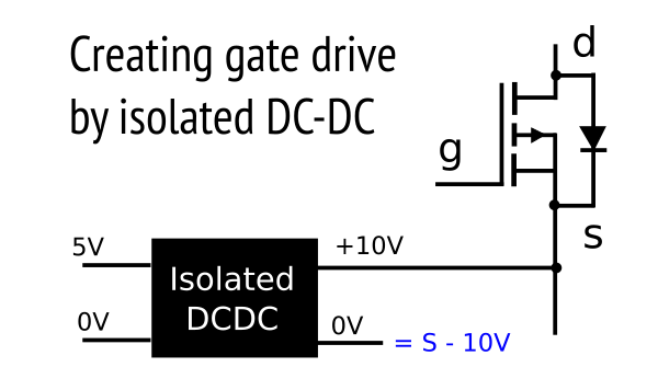
We can simply use an isolated DC-DC converter, with one output side (- for N, + for P) connected to the MOSFET source and the other side being the gate drive level.

Output impedance is very low allowing fast gate drive.
It's floating and directly referenced to the MOSFET source
If we connect the +10V output to the MOSFET Source, the OV output will always be at "source - 10V", ie, exactly the right gate drive voltage
Nothing about it requires system 0V connected, everything on the isolated side of this DC-DC converter is referenced to the switching voltage
Gate voltage cannot get away from the Source - 10V, since it is referenced to Source, so exceeding the Vgs limit should never happen
The solution is expensive in physical size though and not that cheap. But it nails several critical problems.
Solution 2: Switching the floating gate voltage
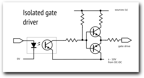
We can use an optoisolator channel to decouple the isolated gate drive level from the DC-DC converter from the switching signal. That gets us out of various difficulties around the gate drive level being below ground or above 40V referenced to the switching signal 0V.
Now we have our own isolated domain for gate drive, we can use a discrete optoisolator with his output directly referenced to that domain.
Solution 6: Removing the need for 0V reference on switched side
You might still want it so you can measure the voltage of the switched side, but with the DC-DC converter and optoisolator scheme, there is no longer any need for the switching 0V reference in the switching circuit. Everything there is floating and referenced to the MOSFET Source, which as we will see becomes the highest of the two potentials on either side of the switch, minus a diode drop if the switch is off.
Solution 4: Making the switch commutative
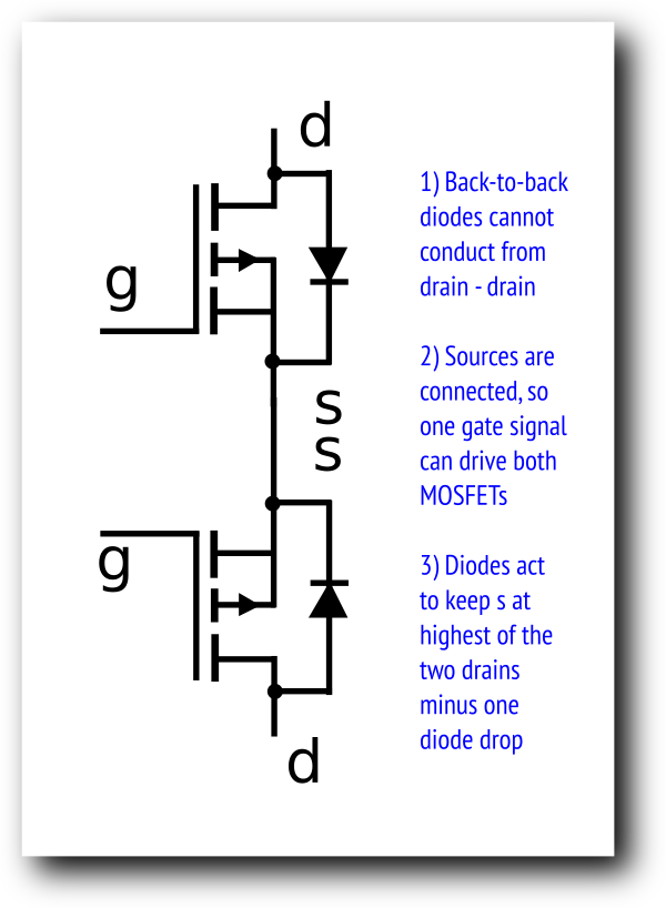
We cannot eliminate the parasitic diode on the MOSFET. But we can add a second identical MOSFET in series with its parasitic diode in the opposite direction, effectively blocking current flow between the drains via the diodes.

Now whatever the situation at the two drains, the diodes cannot conduct on both sides simultaneously and pass current from drain-drain without the MOSFET actually being on.
Instead the drain with the highest potential will set the bias on the combined source pins of the two MOSFETs, minus a diode drop when the MOSFETs are OFF. We don't care what that is, but since we will use the source pins as our reference for the floating gate bias, we need it.
Now whichever way you connect the voltage source and switched output, it meets the same situation, and no current passes without the MOSFET being on. We can monitor the combined source pins and estimate the highest drain voltage even when the switch is off.
This solves the "uncontrolled parasitic diode conduction" problem, but it creates a two new, smaller problems:
1) the parasitic diode was actually useful snubbing negative flyback currents created when the load was somewhat inductive. We therefore need to add back a diode on either side of our switch (to system 0V this time) to snub negative excursions.
2) We doubled our Rdson by making the switched current navigate through two MOSFETs instead of one. We can mitigate it by using slightly more expensive P Channel MOSFETS with 10mR Rdson, giving a manageable 20mR total. (Originally I was using cheaper P channel MOSFETS each of 20mR).
Solution 1 & 3: Isolated, active gate drive for on and off
We can use a discrete bipolar totem pole circuit to actively force the gate between source and the gate drive voltage rapidly, without relying on pullups.

The fact we control the gate from a discrete optoisolator simplifies controlling it, as we can directly reference the transistor output of the isolator to the floating S - 10V.
Solution 5: Protecting against reversed / negative voltages
We can detect that either side of the switch is lower than a diode drop below system 0V (if they bothered to connect that), and turn off the MOSFETs. Now we have two MOSFETs, with back-to-back parasitic diodes, no fault current can flow through the diodes with the MOSFETs off, so we just need to turn the MOSFETs off when we see negative voltages.
However that means if the power polarities were reversed, we have left the system 0V connected at up to +30V. If we have digital connections using that system 0V reference, that means a low level on them appears to be -3.3V compared to the effective system 0V, or +26.7V compared to the intended system 0V.
The solution to this is a comparator to monitor if either side of the switch is more than a diode drop below ground, and an N-channel MOSFET that can disconnect the external ground, as well as the high-side switch.
Rerun Relay Race
| Feature | Relay | Single MOSFET | Dual isolated MOSFET scheme |
|---|---|---|---|
| Isolation of switched power from control signal | Yes | No | Yes |
| Tolerant of spikes and transients | Yes | No | Yes |
| Four-quadrant power switching (current +/-, voltage +/-) | Yes | No (blows up at high currents) | 2 quadrant but protected |
| Low insertion loss to switch | Yes | Usually | Yes |
| Requires 0V reference of switched voltage | No | Yes | No |
| Fragile against short transients without precautions | No | Yes | No |
| Automatically OFF when unpowered | Yes | Not in one direction | Yes |
| Switching speed | ms | us or ns | us |
| Switching bounce | Yes | No | No |
| Marketing value | low | higher | higher |
What we learned this time
MOSFETs need quite a bit of support and adaptation to "look like a relay" generically.
For switching, the MOSFET wants to be either "enhanced", ~10V below the switched voltage for P or 10V above for N, or off (gate = source).
Integrated MOSFET gate drive solutions don't apply for a generic switch application, because they target the much more common buck regulator switching application and contain features that break generic switching
Inbetween OFF and Enhanced, there is a linear region which can lead to high (fatal) dissipation in the MOSFET
The parasitic body diode of the MOSFET defeats operation of the MOSFET as a switch in one direction, the diode is "always on". We can solve it by using two MOSFETs back-to-back
Switching isolated voltages is more challenging, but we can avoid most of the problems by declaring the combined sources of the two MOSFETs its own isolated domain and interacting with it via a DC-DC to generate the enhanced gate level, and an optoisolator to control it.
Bipolar transistors are still useful in a totem-pole configuration for active gate control in both on and off switching
