ICE5 Hyperbus DDR, PLLs Implementation tips
Hyperram DDR on ICE5 FPGAs
I was able to successfully implement a set of VHDL components for hyperbus on ICE5, including the DDR bus interface with quadrature clocks and a round-robin memory arbitrator. It's able to operate at 64MHz / 128MBytes/sec on a normal inexpensive ICE5 FPGA using inexpensive 1.8V 64Mbit Hyperram.
However it wasn't straightforward. There are no DDR sample VHDL components and no documented "vital" VHDL platform components either. So here are some tips for fellow strugglers.
TIP 1: Register the hell out of everything
It's probably already obvious you must use DDR / registered IO cells for the 8-bit data bus, but you also need to do it for the aux signals like the output clock differential pair and nCS. I didn't do it for RWDS but I probably should have; it can work without it so far but there may be extra constraints needed to keep it like that.
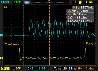
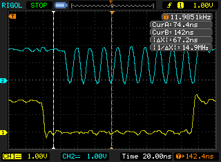
In particular Hyperbus needs to gate the external differential clock, this needs special care using two DDR output cells to provide the correct phases at low skew. Hyperbus clock has a requirement to be gated, and from the + pair member's point of view, low when idle. This requires additional clock sync management because the output clock for the DDR clock IO cell is 90 degrees retarded compared to the logic clock. It can be made to work right but it's a struggle. Here is what a 1 wait block / 3 waitstate / 5 word burst looks like for the + and - clock pair members.
DDR-aware IO cells
So what goes on in the DDR-aware IO cells?
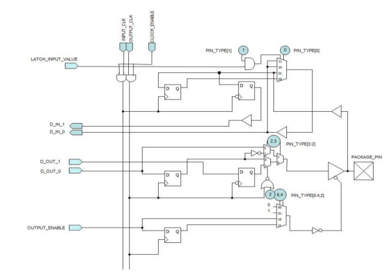
The cells provide four flipflops each, two for read and two for write. For DDR output you actually provide it two bits at half the DDR rate: the cell itself deals with sampling the input data and driving the FF to the output on alternate phases. Because the IO cell FFs are the last thing in the signal chain, and they are clocked by global clock lines, the result has very low skew over the whole chip. As we saw though, the DDR output FF clock must be 90 degrees behind the external clock used to sample the data.
Similarly for input, two input bits are provided and each latch the data state on the alternate edge of the input global clock, so it generates two bits at the rate of the global clock, from one pin.
These features are aimed at bringing the global clock right to the very end of the signal chain at the pin / ball, so there is an absolute minimum of skew. This was always the focus of placing and routing for FPGAs, but with DDR it becomes an issue even inside the clock phases, dealing with it like this in the IO cell is necessary for reliable operation at high speeds.
Registering pieces implies pipelining, that you must arrange the data changes a clock early and the IO cell updates on the next clock. That requires some care to understand when things changing in the VHDL actually take effect outside the chip.
TIP 2: Pieces needed for DDR operation on Hyperram
Generate and output tightly skew-controlled differential clock, allowing for gating cleanly without runts
Quadrature clock generation (using the PLL)
Use DDR FFs built into IO cells for input and output
Clock other critical signals like CS also in its IO cell to control intra-FPGA skew
Distribute output clocks between 0 and 90 degree clock sources
TIP 3: Differential outputs on ICE5
ICE5 can issue differential output clocks, it uses a nice trick using the global clock routing bringing the clock to the IO cells, which may be anywhere in the bank, and setting the cell to DDR mode. The two DDR output phases are set according to the desired output inversion, per pin. The results are nicely locked in phase
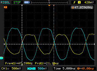
That's quite a smart trick, since the global clocks have low-skew routing to all the IO cells already, and it gets away from making special fixed pin relationships for the differential pair.
TIP 4: Quadrature clocks on ICE5 PLL
Clocks
"in quadrature"
+90 degrees in phase
"center aligned" (the term used in hyperbus)
mean that there are two clocks of one frequency, locked in phase, and that one lags the other by 1/4 cycle.
Assuming a square wave of equal proportions for both parts, that means that one clock's edges will occur in the middle of each of the other clock's stable parts. This is very useful for changing data as far away as possible from when the receiver will sample it.
This +90 degree phase pair relationship is found in many areas of electronics, especially RF, but also things like optical shaft encoders.
Quadrature clock generation via PLL
DDR clocks have a special requirement if they will operate efficiently. Since they pass data on both edges of the external clock, it's not enough to simply have the clock with those edges: they also require a locked quadrature (90 degree phase offset) clock to trigger the updates and captures in the IO cell in the middle of each external clock phase. This is not something you have typically lying around and it's hard to reliably generate it out of nothing; you'd have to halve or quarter your actual clock and do it by hand.
DDR TX Data                =X===X===X==
DDR TX Clock (internal)    _/^^^\___/^^
DDR TX clock (external)    ___/^^^\___/
Single data-rate clocks can readily provide a second set of clock edges at a fixed 180 degreee phase offset, simply by using upgoing edges to update data out and downgoing edges to sample it at the receiver, or vice versa.
SDR TX Data                 =X=====X=====X===
SDR TX Clock (int + ext)    _/^^\__/^^\__/^^\
Then the send and receive actions are locked in phase, the setup and hold time is consistent and data integrity can be assured. But DDR uses both 0 and 180 degree edges in the name of throughput, so this trick is not available and the 90 degree clock becomes necessary.
The usual way to solve this is pass the clock through a PLL, and when it is resynthesized, also output a quadrature (+90 degree phase) version of the same clock. The 90 degree clock will have edges in the centre of the 0 degree clock phases. Even though it's a relatively low-end FPGA, the ICE5 PLL IP can generate quadrature clocks, so you can just feed it your normal clock, set it for x1 operation with 0 and 90 degree outputs. (The PLL wizard crashes, but it dumps the register settings first so you can fill them in on a VHDL component copied from the internal "vital" VHDL file mentioned above.)
The IOs that the PLL bind to have various restrictions related to what kind of other signals may be using the IO cell with the PLL and nearby, and the restrictions differ with the select PLL mode. That forced several hours of experimentation with the PCF since it was unexpected... in the end it was possible to find a way to enable the PLL with only three IOs having to be rearranged / reworked. (That's quite annoying since if the Lattice "breakout board" had not broken its FPGA PLL, I would have tested this beforehand and avoided difficult surgery.)
At any rate write the VHDL first and make sure the placer has no "nonfatal fatal warnings" announcing it's ignoring your pin constraints and continuing to place the design (!) There are many constraints about clock inversion and neighbouring IO cell usage that cost little if the placer has a free hand to pack the IO.
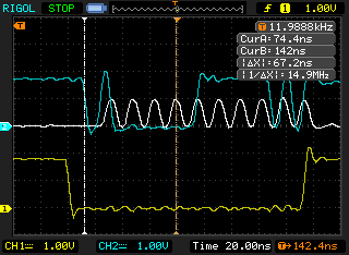
In this picture of hyperbus operating at 64MHz / 128MHz DDR, the yellow trace is nCS to the HyperRam, the white trace is the noninverted differential side of the 90 degrees phase offset PLL clock, and the blue trace RD7 during a 5-word burst.
The 0 degrees phase offset PLL clock (not shown, but 1/4 phase earlier than the white clock) is used to generate and update the blue data; the 90 degree (white) clock tells the receiver when to sample the data.
You can see how the edges of the blue data are offset by 1/4 clock phase so the clock occurs in the middle of a bit.
Since it's DDR, each edge of the white clock represents one bit, so that data going out on RD7 for the 5 words / 10 bytes burst is 1111110101.
Hyperram eye diagram
Hyperbus doesn't seem to specify any particular eye diagram, I guess the reason is that the bus mandates that it should be Hi-Z for periods during the transaction, which make it impossible to provide standard time / voltage pass-fail mask regions since the Hi-Z periods wander through it (pullups are enabled to stop the bus floating for long).
Here is my eye diagram for RD7 with the bus working heavily at 64MHz single-rate clock (128MHz / 128MBytes/sec DDR rate), using the ICE5 IO pieces discussed above.
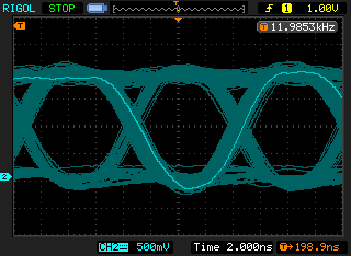
The two lines above the bottom section are related to the tristate periods, due to different sized bursts sometimes the scope triggers and at the bit we're measuring at +200ns, the transaction has already completed and the bus is Hi-Z being pulled up gently, so these can be ignored. This is on a two-layer PTH prototype with the HR running at 1.8V via an LDO.... the eye diagram is extremely clean considering the clock came from a ring osc and went through a PLL.
TIP 5 : Bus protocol optimization
There are several ways you can squeeze bandwidth out of Hyperbus compared to the default.
You must get your basic bus read and write functionality working before you can do these optimizations, including for zero-wait writes.
Optimization 1: Wait states
The Tacc Hyperram parameter is specified in absolute time, 40ns for read, 36ns for write for my device. And the chip defaults to expecting a count of wait states that matches its fastest clock, which comes out to 6.
If you're not operating it at near its fastest specified clock rate (166MHz for my chip, when I am constrained to 64MHz by the FPGA), you can inform the Hyperram to use a smaller number of your slow clocks that meets Tacc. In my case, it only needs 3, the smallest settable number. So we save 3 or 6 clocks depending on if the chip asked for double wait or not.
You can set this in b7..b4 of configuration register 0.
Optimization 2: Allow single waits
By default, Hyperbus comes up always telling you that it requires two sets of wait state waits for each transaction, that's 12 clocks by default. And these are SDR clocks, it's 24 DDR clock edges.
This allows you to make a simple BIU that doesn't have to take care about negotiating it inside the transaction. However these waits are quite expensive in latency, you should instead monitor RWDS and dynamically figure out how many wait clocks are needed. As often as the peer chip will allow you (which is very often) you can lose a set of waits that way, somewhere between 3-6 clocks on most transactions.
You enable this by clearing b3 on configuration register 0.
Optimization 3: Crank up the clock
Since you are forced to use a PLL to generate the quadrature clocks as we discuss later, might as well change up the clock ratio to a bit below whatever the FPGA timing will allow.
My base clock is 48MHz, but I can convert it at 4:3 using the PLL and end up with 64MHz; the FPGA timing has slack up to 70MHz. This can probably be pushed higher with more pipelining, but I have more bandwidth than I need already.
TIP 6 : Hyperbus nReset
Hyperbus mandates a Power-on reset, so I decided we didn't need to deal with the nReset bus pin and tied it to 1.8V under the BGA. This was a little bit brave, because it turns out if you do resets without a powercycle which is common during development, state is held across sessions in the hyperram configuration registers.
For example if you optimize the waitstates to 3, when you reset you now have two possible numbers set up in the waitstate register: 6 from POR or 3 from warm reset. Although configuration space writes are specified to operate with no wait states at all times and so work unconditionally, reads use the chip's currently configured number of waitstates, so reading even the ID registers is not possible unless your side is set to use the expected number of waitstates at the hyperram.
After some experimentation it turns out you can loop through the possible wait states of 3, 4, 5, and 6 checking if you get a reasonable result from the ID register. After that you can use the "detected" current wait state number to confirm the ID registers and force the wait optimizations into the configuration. So it seems you can do without nReset.
What we learned this time
If you do the digging to uncover the undocumented VHDL prototypes, there are enough pieces there to get a proper DDR bus interface inside the FPGA in VHDL, and operate Hyperram at 64/128MHz DDR reliably
Again the quality of the actual FPGA, signal quality, PLL lock and jitter behaviour, is very good
