Getting started with ICE40 Ultra FPGAs
ICE40 Ultra Introduction
In terms of price the cheapest way to get usable amounts of programmable logic is still the ancient cpld.
However the cheapest ones are very resource-starved and there is little room for tricks with their crossbar structure.
The cheapest FPGAs are now becoming competitive on price with the old CPLDs, this article discusses a new variant of Lattice's ICE40, ICE5 or "ICE40 Ultra".

I decided to write an article about it because there are numerous puzzling things about their dev kit and even after spending a day on it, what I found should certainly help other victims. To be fair some of it is the usual problems about shipping Linux binaries but many of the issues are completely self-inflicted by Lattice.
ICE40 Ultra dev board
http://www.latticesemi.com/Products/DevelopmentBoardsAndKits/iCE40UltraBreakoutBoard.aspx
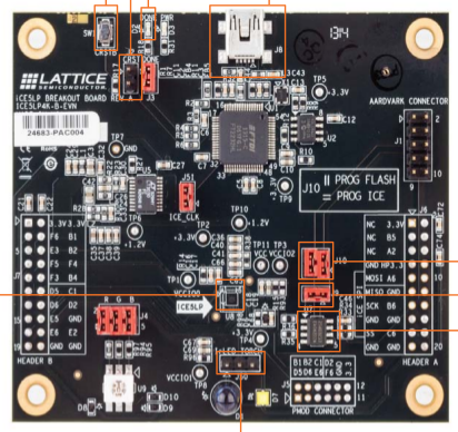
The dev board is nice and cheap at USD50 from Digikey. But there is quite a long list of confusions and puzzlements about it and its software.
Strange Choice #1
The dev board features the "4K" CLB ICE40 Ultra silicon, the largest version offered (actually, it's like 3.8K CLB but never mind).
However despite this being the largest chip in terms of internal resources, they provided it on the dev board only in a tiny 36-pin BGA variant. That means the chip on the official dev board has less FPGA IO than even the modest 48-pin package I intend to use. Packages available for that chip go up to hundreds of pins.
This is a major issue for me actually, since I need 12 pins to communicate with a peripheral at high speed, but the largest number of uncommitted IO on the dev board on one IO bank is 10. The other banks have 6 and 1 uncommitted IO respecively.
Strange Choice #2
The FPGA IO banks have individual Vcc, so they can bank-by-bank be assigned different IO voltages, which is nice and flexible. Indeed the peripheral I want to prototype with this board is 1.8V but the host device it will connect to is 3.3V, so I rely on it.
On this dev board, all IO banks are hardwired to 3.3V. There's no jumper select. This makes the board of very limited use.
Annoyance #1
The dev tools are downloadable for free, which is normal now in the low-end market. And they're available for Linux as well as Windows.
However they require you to install a macrovision license file, tied to a mac address. This file is also for free, but the licensing stuff just makes trouble for no gain to anyone, not even Lattice.
I registered the license to my wlan device mac, which is the main network interface on this machine. However starting the gui failed with "Licensing Error 19" (this is on Linux, with $0 downloaded vendor software using a pointless $0 downloaded vendor license file). Googling around revealed that the macrovision license library is used on a bunch of other proprietary software, and the issue is it just looks for the mac on "eth%d" and ignores network interface names that were not popular in 1995.
The "solution" is just rename the interface to its expectation
sudo ip link set wlp3s0 down
sudo ip link set wlp3s0 name eth0
sudo ip link set eth0 up
sudo systemctl restart NetworkManager
Strange Choice #3
The dev board (the official name is "breakout board") ships with a test image that lights the red part of an RGB LED and sits there.
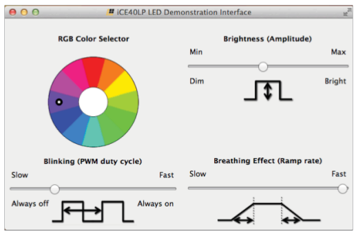
They have made a Windows + Mac (but no Linux!) GUI app that lets you communicate with the FPGA and change the PWM state of the RGB elements. And they give a URL on a piece of paper where to download that to "get started".

But they don't ship that HDL as an example with their GUI and HDL tools. There is an ancient example called "blinky" alright, but he does not have PCF (pin layout mapping files) for SWG36 (aka WLCSP36) package variant that is actually on the dev board, nor any other package used by ICE5. It looks like it is some ancient test app inherited from older variants that has fallen out of favour.
Incredibly, they provide the BITSTREAM for the demo for download, but not the HDL.
http://www.latticesemi.com/Products/DevelopmentBoardsAndKits/iCE40UltraBreakoutBoard.aspx
But they do spend three pages in the dev board pdf describing the SPI protocol to control the FPGA-logic PWM they're not giving the HDL for.
This makes no sense: nobody is buying an FPGA dev board to "get started" with some crappy windows app doing PWM on a binary-only FPGA bitstream.
People need all the sources of some simple known-good project to build and adapt to get through learning the flow quickly. It's fine if it's trivial and just blinks the LED without dependency on Windows, working USB / UART, and SPI, what is needed to "get started" on is yet another variation of the build flow and different tools.
It seems necessary to port blinky and use the schematics in the short PDF that came with the dev board to get started from scratch!
Annoyance #2
Lattice have separate tools for "programming", which are also available for Windows and Linux. The Linux version comes in a choice of 32-bit or 64-bit RPM, which is nice.
Why is it an "annoyance" then? ---->
Annoyance #2.1
The 64-bit RPM installed easily enough and I had a look in the package to see how to start it, because there is no information in the dev board PDF.
Annoyance #2.2
It installed itself in /usr/local in defiance of packaging standards, and thus can't integrate with your Desktop Environment. Not that it tries.
Annoyance #2.3
I found what turned out to be a script /usr/local/programmer/3.7_x64/bin/lin64/programmer, which is pretty strange but OK.
Annoyance #2.4
I started the script, it blew a segfault with no feedback.
Segmentation fault (core dumped)
Later I ran its component part by hand so the console feedback was still enabled, and learned
get one help index file /usr/local/programmer/3.7_x64/docs/webhelp/eng/tool_programmer.xml for tool PROGRAMMER.
get one help index file /usr/local/programmer/3.7_x64/docs/webhelp/eng/tool_programmer.xml for tool PROGRAMMER.
libusb couldn't open USB device /dev/bus/usb/001/008: Permission denied.
libusb requires write access to USB device nodes.
libusb couldn't open USB device /dev/bus/usb/001/013: Permission denied.
libusb requires write access to USB device nodes.
libusb couldn't open USB device /dev/bus/usb/001/008: Permission denied.
libusb requires write access to USB device nodes.
Segmentation fault (core dumped)
So it basically craps itself if it can't open (any?) usb devices, at least if it can't open the one it likes after the scan. I guessed this was the problem and re-ran it with sudo.
Annoyance #2.5
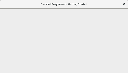
On starting this from the console now with sudo, I still get no feedback, but it doesn't crash... just shows an empty grey dialog with a titlebar.

This is quite rough to google for, at least nobody else seemed to have met it with Lattice. Strace didn't show anything and there was no console or other logging. Eventually I went into the "programmer" startup script and checked with ldd where the libs were coming from, the ship their own Qt4 libs. I moved these out of the way so it could use the system ones, but this didn't help.
Finally I started running their startup script env changes one by one by hand on the commandline and executing their main app binary directly. This got me console logging, the startup script was quenching it
X Error: BadAccess (attempt to access private resource denied) 10
  Extension:    130 (MIT-SHM)
  Minor opcode: 1 (X_ShmAttach)
  Resource id:  0x15d
X Error: BadShmSeg (invalid shared segment parameter) 128
  Extension:    130 (MIT-SHM)
  Minor opcode: 5 (X_ShmCreatePixmap)
  Resource id:  0xde
  ...
After checking it wasn't selinux, finally those keywords got me some google company in my misery, what finally fixed it was feeding it QT_X11_NO_MITSHM=1 in the environment.
Annoyance #2.6
After all that, the "programmer" app starts up wanting to use JTAG / Boundary Scan semantics, which are not supported by ICE5 (its configuration is predicated around SPI), although it's possible to chain SPI so it's unclear if that would work even so. But the scan chain autodetect fails.
Googling around this seems to be related to ftdi_sio Linux driver binding to their onboard dual usb - serial chip used to do SPI bitbanging.
However with the lack of balls on the dev board, there is no point wrestling with those tools, since I can't test the things that I need to with it. Instead I hacked the dev board to be configured from my own host directly using SPI and can forget their "programming" tools.
Strange Choice 4
The official Lattice "breakout board" doesn't follow Lattice's own recommendations about power supply sequencing, from document EB87 "ICE40 Ultra Breakout Board"
The power supply sequencing does not conform to the NVCM boot requirements as specified in DS1048,
iCE40 Ultra Family Data Sheet. The user may encounter intermittent boot success and/or higher than specified
startup currents when attempting to boot from NVCM.
Still this is interesting looking at what shortcuts passed at lattice compared to the sermons in their datasheets:
the complex power sequencing can be violated if you don't care about boot from the internal flash and briefly higher current at startup
the unwelcome 2.5V rail (it means this chip demands 1.2V, 2.5V and 3.3V) can be hacked up from 3.3V via a diode drop (with no bypassing) if you don't care about internal flash.
if you don't care about the PLL then you can just short the PLLVCC to 1.2V instead of providing the "required" filter network
and the world keeps turning.
Shortcuts are fine but in a "breakout board" if it has a chip with a PLL on it as this does, you reasonably expect to be able to use the PLL. This board breaks the PLL by omitting the filter. It's unreasonable.
Minimal toggle example
The board gives us a 12MHz clock on C2. The test vhdl just toggles a flip-flop with it and sends it back out on F4. Both of these are on Bank 1 (not that it matters since everything is forced to 3.3V)
library IEEE;
use IEEE.STD_LOGIC_1164.ALL;
use IEEE.STD_LOGIC_ARITH.ALL;
use IEEE.STD_LOGIC_UNSIGNED.ALL;

entity icetest is
    Port (
           clk     : in  STD_LOGIC; -- C2 BANK1 IOB 25B_G3
           toggle  : out  STD_LOGIC -- F4 BANK1 IOB 11B_G5
     );

end icetest;

architecture Behavioral of icetest is

signal t : STD_LOGIC;

begin

toggle <= t;

process (clk)
begin
if (rising_edge(CLK)) then
      t <= not t;
   end if;
end process;

end Behavioral;
You need a "Place and Route constraint file" (as opposed to design constraint file) to map the logical ports to actual balls on the right chip, create this in a .pcf file in your project dir and add by rightclick on P&R flow | Add P&R files | Constraint files
set_io clk C2
set_io toggle F4
Careful, the ball names are case-sensitive.
You'll find a 6MHz square wave on F4 (J7.8)
Annoyance #3
Attempting to synthesize some test VHDL gives
****************************************************************

Error: platform linux_a_64 4.6.4-301.fc24.x86_64 is not supported

****************************************************************
We must inform ./lscc/iCEcube2.2016.02/synpbase/bin/config/platform_check that 4.x Linux kernels exist.
case $VERSION in
    4.* | 3.* | 2.4.* | 2.6.*  )
Afterwards it can synthesize the bitmap, it puts it in lscc/iCEcube2.2016.02/sbt_backend/Projects/projname/projname_Implmnt/sbt/outputs/bitmap/icetest_bitmap.bin. As the config app note says, it's ~72KBytes for the 4K Ultra.
Oversight #1
There is no way to stop the FTDI chip on the "breakout board" driving the FPGA config SPI CS (aka "SS_B") and SPI CLK. The other signals MOSI, MISO can be disconnected via J10, and you can disconnect the onboard SPI flash from seeing the config CS using J9.
The SPI config signals appear on (unpopulated...) connector J6, so it's not unexpected we might use them.
The FTDI chip drives CLK and SS high by default, so they can be overridden externally if you leave the FTDI interface alone on your PC. However if your CS line has plans around a pulldown, this will wreck them.
What did we learn this time?
Lattice ICE40 Ultra "breakout board" does not have enough uncommitted FPGA IO (just 17) to allow development for anything but the smallest-package variants
Only 3.3V IO standard is supported on the board, despite the chip allows other standards
The board violates Lattice's own design requirements at least 3 ways, I guess these violations are also somewhat blessed if you don't care about the things they break.
The chip has a PLL but the board design deliberately breaks it, too bad if you wanted to prototype with it
No worked HDL + pin mapped examples, just a useless binary bitstream. You are on your own.
Brain the size of a planet, the board comes up with a red LED and sits there
pointless free ($0) license file for free ($0) tools that just exists to make trouble
JTAG programmer tools doesn't work OOTB on Linux
Nobody at Lattice has a box with a 4.x kernel (out for a year now), generally it's much more of a struggle than it should be to get the tools working on Linux
Somebody at Lattice needs to have a vision quest about why people want an FPGA "breakout board", it's not because they have a mac and want a GUI app to control an LED.
the chip is easy to configure over SPI from your own host
the FPGA itself seems very good to me. But the breakout board is a waste of time and money.
