Silego GreenPAK crosses Analogue, CPLD and FPGA
Silego GreenPAK
Silego http://www.silego.com/ is a small semiconductor company with some very interesting products.
Their GreenPak devices basically combine a OTP CPLD type crossbar with both digital assets like latches and FPGA-style Lookup Tables (LUT), and analogue assets like 8-bit ADC and DACs, and analogue comparators. The routing for all the assets is controlled from a 2Kbit OTP array, loaded into volatile configuration FFs at power-on.
http://www.silego.com/uploads/Products/product_365/SLG46621r111_03252016.pdf
Basically they are like a cheap microcontroller with crossbars + random logic instead of the cpu to move things between peripherals.
They are very small and very cheap, at quantity down to US$0.20, and the development tools are also inexpensive.
The overview of the die assets is like this
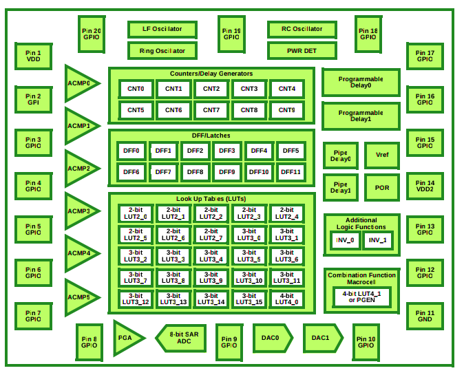
That price is so low, it means these can be considered to replace discretes, and these have advantages like onchip oscillators and sequencing logic, low power and being smaller than the equivalent discrete real-estate.
OTP but also reconfigurable
But potentially the killer thing about them is although the initial state can only be programmed one time in the OTP, actually the active 2Kbit configuration state may be changed dynamically over I2C. Their dev board uses this to emulate your design in realtime, "programming" the configuration state into the volatile registers only, but if there are additional smarts on the device it's designed into enough for i2c, this dramatically increases the value of the assets in the chip.
Back in the 1990s when I was using the early Xilinx FPGAs, XC2064, I reverse-engineered the bitstream so I could similarly set "constants" like initial FF states dynamically instead of setting them in the development tools, or having to use assets to hold them in explicit registers: this radically improved what could be done with these small devices. So it definitely adds a whole new dimension to these chips: and the configuration bit mappings for GreenPak are already in the public documentation.
Silicon breadboard
In effect the crossbar means that these tiny chips are populated "breadboards" with digitally programmable interconnect.
Because of the fixed set of assets on the die, and other restrictions and constraints, the key to leveraging the crazy price:performance ratio is properly understanding what's in there and how it can be used.
For example although the digital assets seem a scatty mix of LUTs and counters, in fact there is enough in there to make complex state machines that may be enough to replace small microcontroller tasks.
These chips are tiny...
Silego provide two types of package and samples with the dev board, and two types of test socket you can mount the chips on the dev board with. I am only interested in the "larger" SLG46621 one (2mm x 3mm!), but the chip dimensions are incredibly tiny, there is no way to mount them for prototyping without a paste mask and hot air rework tool. The pin pitch is 0.4mm.
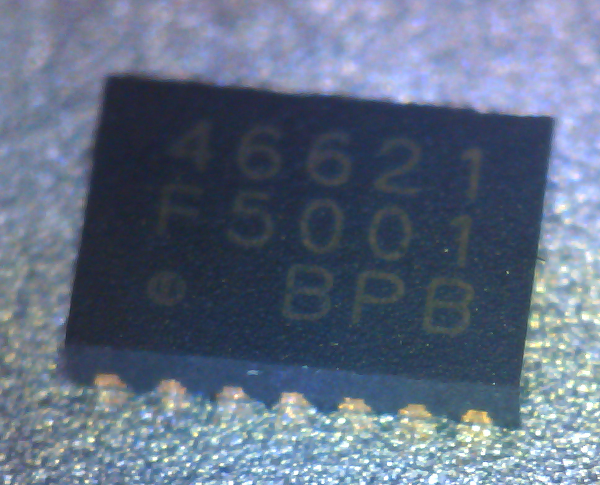
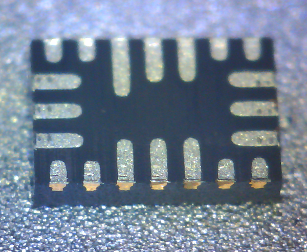
The dimensions of the test socket are correspondingly insane as well
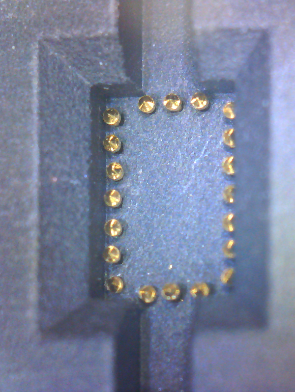
However due to the prototyping flexibility, you can be pretty sure your device is going to work before committing to a pcb and paying to get the chips mounted.
GreenPAK dev tools
Installing on Fedora
There's good news and bad news... the good news is Linux is a supported platform . The bad news is that comes in the form of .deb packages only. Well it's good news for you if you are on Debian or Ubuntu.
I was able to get it to install on Fedora by
dnf install dpkg- unzip the distribution zipfile to find the two .debs
dpkg -x <32-bit deb> .rsync -a lib/* /librsync -a usr/* /usr
Afterwards, some i686 pieces are needed
dnf install libusb.i686 qtwebkit.i686 glibc.i686
Then you can run GPLauncher as a normal user.
Graphical tools
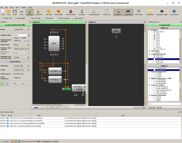
Silego have done a nice job with the tools, but they are all working from a hardware engineer's point of view. That is, you operate in a "schematic editor", "wiring up" assets on the die. In particular it's permanently in your face due to the UI design that the silicon architecture has two disjoint crossbars with a restricted number of interconnect between them.
No HDL support
While this is true, for decades CPLDs with the same basic architecture have offered HDL (Hardware Description Language) support for expressing the design. In the case that you want a complex state machine from the available pieces, it's going to be timeconsuming to "wire it up" and then inflexible and painful if you want to change it. Similarly if you want to port your design to another GreenPak part, you will have to start over. Abstracting the design into an HDL gets you away from those kinds of detail at the cost of losing exact control over what goes where, but often, that's "control" you are very glad to cede.
If you think about publishing work in git, the flow of editing source text in a distributed way is very well established and contributions are easy to integrate. With the graphical tools, a binary is in the repo and there is no concept of a diff.
So in many ways graphical hardware design is something with a past and no future.
Update 2016-05-06: Nascent FOSS HDL support
I was contacted by Andrew Zonenberg to tell me about his project on Github providing a Verilog compiler for the Silego GreenPak 46620.
Let's hope Silego consider supporting that, because being forced to work on a floorplan to implement what is basically code is now extremely unfriendly, even when there are only a couple of dozen assets to wire up.
Hello World experience
From spending a few hours with it, I learned
it works out of the box quickly
the flow is edit the circuit, check for design rule errors, then click the 'emulate' button on the hardware window to update the dev board
routing a 2-input LUT to itself as an inverter, and drive a FF clock with the result so it toggles, gets a 38MHz square wave. So the internal self oscillation rate of the inverter is about 76MHz which is pretty nice.
trying to use the hard counters,
the choice of clock source does not include any internal node. The closest is an "external clock" input: you'd have to route the internal node out the chip and back in the clock input it seems.it turns out the OSC macrocell has an "external clock" input that can be routed to from inside the chip.
