Hall-effect current sensing
Dynamic power measurements
There continues to be interest about dynamic power measurements, after some work I did on top of Arm's "Energy Probe" back in 2012. You can read about the various issues I found with that here
https://git.linaro.org/people/andy.green/arm-probe.git/blob/HEAD:/arm-energy-probe-101.pdf
Basically the current measuring amplifier becomes blind below 20mA or so with typical shunts, and there are several other issues around temperature sensitivity and inter-channel matching. The problems are largely coming from the shunt amplifier chosen, which becomes badly nolinear when the voltage across the shunt is near 0.
Another major problem related to the choice of shunt amplifier is the relatively large fullscale voltage drop it expects to measure across the shunt, 165mV. If your voltage rail was only 1V in the first place, this is a completely unacceptable drop.
Hall effect current sensing
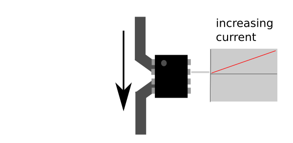
Allegro have a very interesting alternative current measurement technology which inserts almost no losses, less that one mR + the inductance of the SO-8 leadframe. It works by passing the conductor through a Hall effect sensor integrated in the chip, and amplifying the sensor voltage (which is linearly dependent on current flowing through the conductor) as an analogue output.
http://www.allegromicro.com/~/media/Files/Datasheets/ACS722-Datasheet.ashx
This has some pretty impressive advantages:
Almost no voltage drop or power loss
There is no resistive shunt, the power must pass through a few mm of chip leadframe is all, it's quoted as 650*micro*Ohm. So there is no power drop or significant inductance increase in the path: it's possible to insert it on the output side of low voltage / high current regulators.
Isolation
The analogue output side of the chip is galvanically isolated from the power rail being measured. 1V, 1.8V, 3.3V, 5V, 30V, 110V, 230V are all OK. (Never work on stuff directly connected to the mains without taking appropriate safety precautions and using an isolating transformer... this article is about measuring low voltage DC currents)
Bipolar response
ACS722 used here has bipolar response to current moving in both directions. With no current passing, the output is nominally at 0.5 Vcc (1.65V for 3.3V) and it moves higher or lower symmetrically depending on the direction of the current flow.
High bandwidth
Output bandwidth is pin-selectable as rolling off at 20kHz or 80kHz.
Fairly cheap
They are around US$4 in low quantity.
One new issue, magnetic disturbance
Hall effect sensors work by sensing a magnetic field, external magnetic fields are detected indistinguishably from that caused by current passing through the sensor conductor.
Kicking the tyres
Analogue semiconductor datasheets often play a little game with the engineer, they have something about the chip response they don't want to come out and say, but they have to indemnify themselves complaints later, so they must find a way to touch on the subject in a way that they can claim subsequently, "of course that is what we meant by that", or, "obviously a reasonable engineer would have understood from that..." Therefore it's wise to look for what is not said, or not given a graph or specific numbers with a very sour eye and go confirm it yourself before falling in love with the thing.
Basically these kind of solutions that output an analogue voltage for a zero-point have their work cut out reproducing that voltage over production spread of devices, temperature, age and other enemies of analogue determinism. I read in the datasheet that there is a considerable signal conditioning chain including temperature compensation after the Hall sensor and the devices are factory-trimmed to make them give identical response within a few percent.
Even if that is so, the ADC you would use to sample it will have its own problems acting exactly the same across process and temperature, so exactly how that whole thing acts for repeatability needs to be thoroughly understood.
The related graphs for ACS722 are like this:
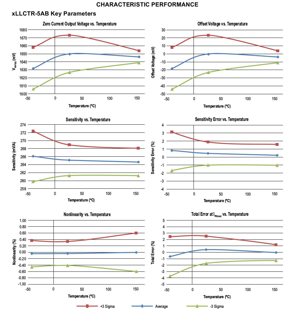
"3 sigma" lines are telling us about the process spread around the average, 99.7% of chips will perform in the area inside the red and green lines. If you are not familiar with how crunchy the Analogue world is, you might find this surprising both that we don't exactly know how the individual chips will perform and that we are not informed about how the 0.3% of chips might perform, presumably Allegro will throw them out so we don't need to concern ourselves.
What is zero?
We already mentioned with no currently flowing, ACS722 output should sit in the middle between 0V and Vcc. But even if ACS722 was perfect, the power regulator for 3.3V won't be, it will differ a little each time.
You can see from the top left graph, if the 3.3V regulator is otherwise perfectly the same every time, ACS722 process spread at 25 degrees is around +/-22mV for the zero point. Well, the output sensitivity for ACS7522 is 264mV per A detected, so +/-22mV corresponds to a per-device offset of up to +/-83mA in detection.
So there is going to be very significant disagreement between chips and at different temperatures about what "zero" looks like. But that's not too bad actually because as a static offset if we measured it and stored it somewhere along with the device, we can normalize all the sensors for their own personal offset. It varies over temperature but actually there's a cunning trick up our sleeves for that we discuss next.
Temperature linearization
All of the graphs above have temperature as their X axis, that tells you the vendor knows the device acts quite differently depending on the ambient temperature. There should not be much self-heating, it takes very little current to operate and there is almost no impedence to the current being measured.
You might think to linearize the response across temperature, we would have to measure the temperature and apply a correction function. However, there is a very cool trick we can perform to linearize it with almost no effort (although, a little bit of cost).
You can see that in 3 of the 6 graphs ("Zero current output", "offset" and "Total error"), the process spread difference is largely a matter of an offset, the three process spread lines actually describe the same shape.
For the other three graphs, if we restrict the operational temperature to between 0 and 50 degrees, which is reasonable for development / bench operation, the graphs then also conform quite well to the idea the process spread simply introduced another fixed offset.
So... so what?
Differential measurement
Normally we would use an ACS722 like this

... he outputs a monotonically increasing voltage proportional to the increasing current he senses.
However if we use two, where the second sees the current flow inverted...
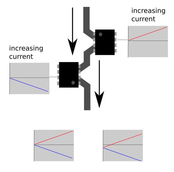
We can effectively make a differential measurement. Temperature and other problems like sensitivity to power supply voltage and aging drift, affect both sensors about the same, and in the same direction, as shown in the bottom right image. If we only measure the difference between the two sensors, we can cancel those annoying effects and become fairly immune to zero drift.
The problem caused by external magnetic fields being detected as current can also be helped by the differential technique, if the second device occupies nearly the same volume as the first with the same orientation, it should be affected similarly also being treated as common-mode noise and removed at the differential receiver.
So after thinking of this differential technique I ordered some ACS722 and hooked them up to a test jig, using a Freescale K64F dev board and the 16-bit differential ADCs on that.
Testing acs722 performance
I hooked the acs722 between a linear bench PSU and a BK Precision 8540 Programmable electronic load.
Since I was using the 5A-rated part, I first checked the gross results in both directions, at 5A scale it performs very well and as expected.
However most interesting current measurements on digital devices tend to involve lower currents, at least some of the time. And we are always interested in an analogue measurement system to reliably detect "zero", which is usually harder than it sounds. By definition detecting "zero" involves system performance at low currents.
acs722 performs very poorly here. If you zoom out, he can indicate the current rate very well, but if you watch him with no load, or any consistent load, he is wandering about all over the place. Here is one ACS722 (ie, "singleended") with a consistent load over 110s... this data has already been averaged over 32 ADC samples, the raw data at ~50kHz is much worse.
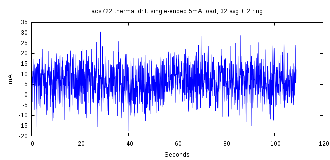
Because of the duration of the excursions, it seems there is signalprocessing inside the acs722 that periodically "autozeroes" the device to counter thermal drift. Thermal drift or noise by itself we might be able to do something about but this semi-processed version that rebases itself at arbitrary times cannot be told from actual signal. Here's the same situation with a 128-length averaging ringbuffer on top of the 32-sample ADC averaging (notice the Y axis is tighter than the first plot)
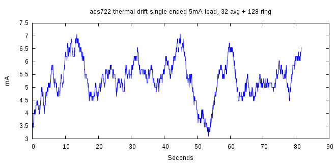
This makes the "drifty" nature of the noise clearer and shows how averaging isn't going to help.
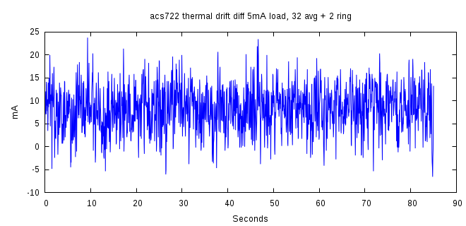
I was surprised by that, so I checked with a 5W power resistor as the load instead of the programmable DC load in case there was some interaction with that, but the results are the same. I also checked the "differential" configuration with two ACS722 back-to-back and the ADC set for differential input mode, but because each ACS722 is doing his own recalibration continuously alone and unsynchronized, ie, it's not a common-mode issue, it's no better.
Conclusion
After these results I went back to the datasheet, they basically tell straight up the noise performance is really bad for small currents.

It means that a measurement of "42mA" as told by the ACS722 may be completely ficticious with no current flowing actually, or actually 82mA is really flowing. Even if it tells you instantaneously 420mA is flowing, you can only trust that number within + / 42mA. And that 42mA noise number is in the "Typical" column, there is no max figure.
Even with heavy averaging (reducing the measurement bandwidth to a few Hz not the 10kHz for parity with AEP) the zero level uncertainty is > 3.5mA meaning you cannot tell signal from noise at all at this low level.
So despite its many good qualities for general current monitoring, at least by itself the ACS722 doesn't seem like it can give useful results as an AEP-style, generic dynamic current monitoring instrumentation.
