Whirlygig PCB
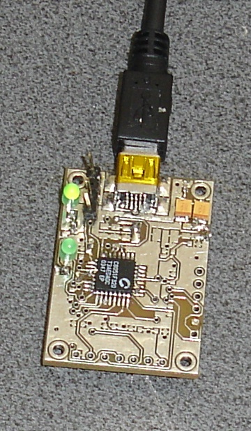
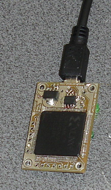
I built the first prototype Whirlygig PCB last weekend, it's working well. For testing I left out the noncritical inductors and some caps. I also found the total current consumption at the USB side is 250mA with the CPLD macrocells in low power mode and 350mA with them in high power mode, comfortably within the 500mA USB budget. I decided to use the higher power mode because it should increase the ring oscillator frequencies and hence the randomness. The CPLD runs hot, around 40 degrees C.


 The second idea was that now we have a pool of oscillators greater than needed at any one time, we can randomly select from them for each output bit operation. So I added an additional 32 oscillator sets (4 for each output bit) which are only used to select which of the pool of 16 we use for any operation. The end result is that at least 8 oscillators from the pool will be unused for each operation, and which oscillators do get used for which bit are individually "random" with "no" correlation between output bits. This makes any attacker's attempt to model the pool oscillator states very tough because there's no longer any knowledge about which bit contains information about which pool oscillator, or even if its state has affected any output bit.
Lastly we now operate from a clock (24MHz) that is 14 times faster than the sample rate. This lets us mix 14 randomly chosen oscillator states by xor before the output is sampled for each bit. Even if two output bits were mixed with the same 14 oscillators, the order would have to be the same as well to get the same result, since the oscillators are never standing still. For this same reason selecting a pool oscillator more than once in the 14 operations is not equivalent to a NOP.
I added another small tweak, all of the random generators shift ther oiginal state by 1 generator on each clock. This is intended to reduce the impact of any hard nonliniarity in individual generator routing on the CPLD.
There were no problems with the PCB, but to save myself a headache working with the crossbar in the CPU I blobbed together pins 26 and 27 on the CPU.
In the next article we look at the random performance again with the new scheme.


Improvements
I took the opportunity to make some improvements: - Added JTAG programming of the CPLD to the SiLabs microcontroller over USB. This allows change or update of the CPLD logic from the host PC without any hardware needed. However because the kernel module blocks the logical USB interface, it's safe from being rewritten while in use. - Changed the random logic. I'll explain the changes and results in the rest of this article. - Decreased the polling rate of the CPLD but increased the total USB random throughput, 1.0MBytes/sec sustained (for as long as you like) by making the code in the microcontroller "multithreaded". You can also plug in more Whirlygig devices to linearly increase random production; the kernel module allows hotplug and unplug without problems and combines the output seamlessly all in /dev/hwrng. - I was pleased to see the kernel module had hardly bitrotted at all, it only needed a one-line edit to build a working module against a current Fedora Rawhide kernel. The second LED lights while the PC is requesting random packets from the device. It lights briefly on plugging it in while the driver's cache is filled, then it only lights when something is using the hard random numbers on the PC.New random scheme
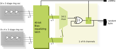
I had three main ideas about improving the random hardware inside the CPLD. First I realized we can decrease predictability by having more oscillators than are used at one time to change an output bit. We have 8 output bits, but we now have 16 oscillator sets. Instead of combining them all, on average several will not be used on any given operation. The second idea was that now we have a pool of oscillators greater than needed at any one time, we can randomly select from them for each output bit operation. So I added an additional 32 oscillator sets (4 for each output bit) which are only used to select which of the pool of 16 we use for any operation. The end result is that at least 8 oscillators from the pool will be unused for each operation, and which oscillators do get used for which bit are individually "random" with "no" correlation between output bits. This makes any attacker's attempt to model the pool oscillator states very tough because there's no longer any knowledge about which bit contains information about which pool oscillator, or even if its state has affected any output bit.
Lastly we now operate from a clock (24MHz) that is 14 times faster than the sample rate. This lets us mix 14 randomly chosen oscillator states by xor before the output is sampled for each bit. Even if two output bits were mixed with the same 14 oscillators, the order would have to be the same as well to get the same result, since the oscillators are never standing still. For this same reason selecting a pool oscillator more than once in the 14 operations is not equivalent to a NOP.
I added another small tweak, all of the random generators shift ther oiginal state by 1 generator on each clock. This is intended to reduce the impact of any hard nonliniarity in individual generator routing on the CPLD.
There were no problems with the PCB, but to save myself a headache working with the crossbar in the CPU I blobbed together pins 26 and 27 on the CPU.
In the next article we look at the random performance again with the new scheme.
